Electromagnetic machine with a deformable membrane

a technology of deformation membrane and electromagnet, which is applied in the direction of electromagnets, dynamo-electric machines, electrical apparatus, etc., can solve the problem of not producing coherent sound waves, and achieve the effect of less nois

Active Publication Date: 2008-01-29
AMS R&D
View PDF4 Cites 35 Cited by
  • Summary
  • Abstract
  • Description
  • Claims
  • Application Information

AI Technical Summary

Benefits of technology

[0010]In addition, the machine is no longer subjected to alternating linear vibration, other than that generated by the motion and deformations of the diaphragm which are small in amplitude and which therefore induce little noise.
[0011]A machine of the invention is thus substantially less noisy than prior machines.

Problems solved by technology

Thus, during the alternating rotary motion of the moving part, the air surrounding the moving part is set into motion essentially by alternating shear, which does not produce any coherent soundwaves.

Method used


Image

  • Electromagnetic machine with a deformable membrane
  • Electromagnetic machine with a deformable membrane
  • Electromagnetic machine with a deformable membrane

Examples


first embodiment

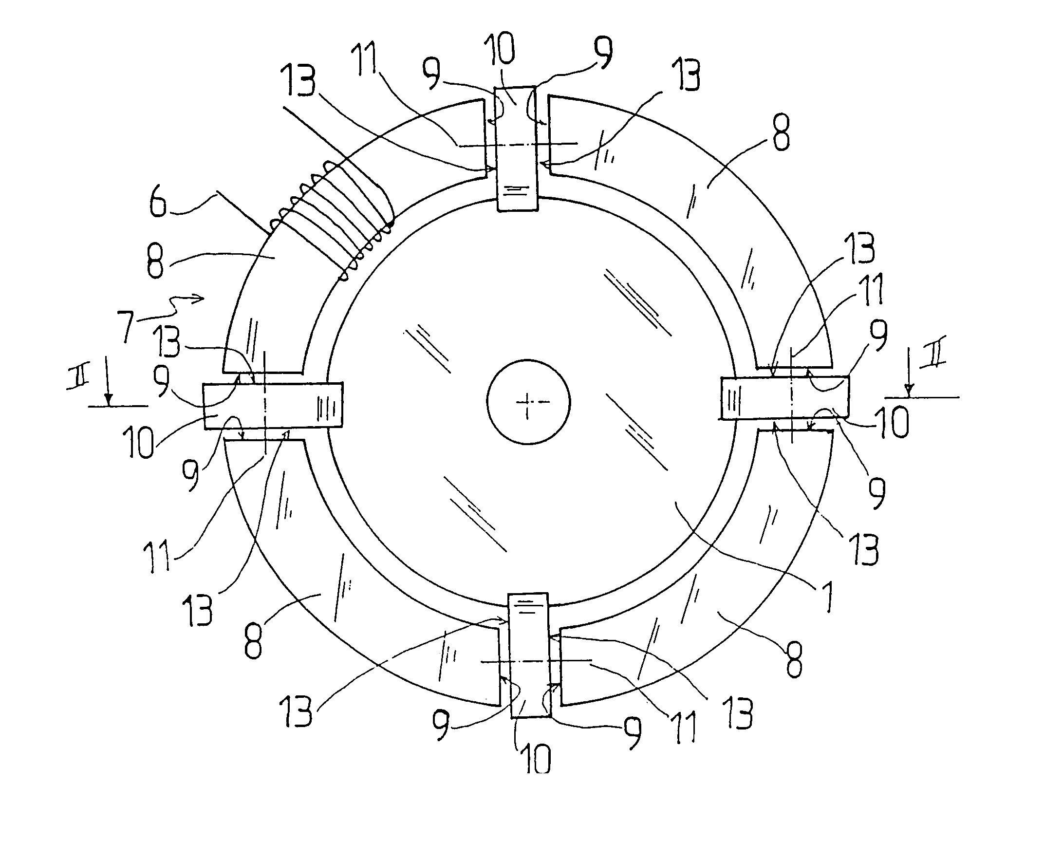
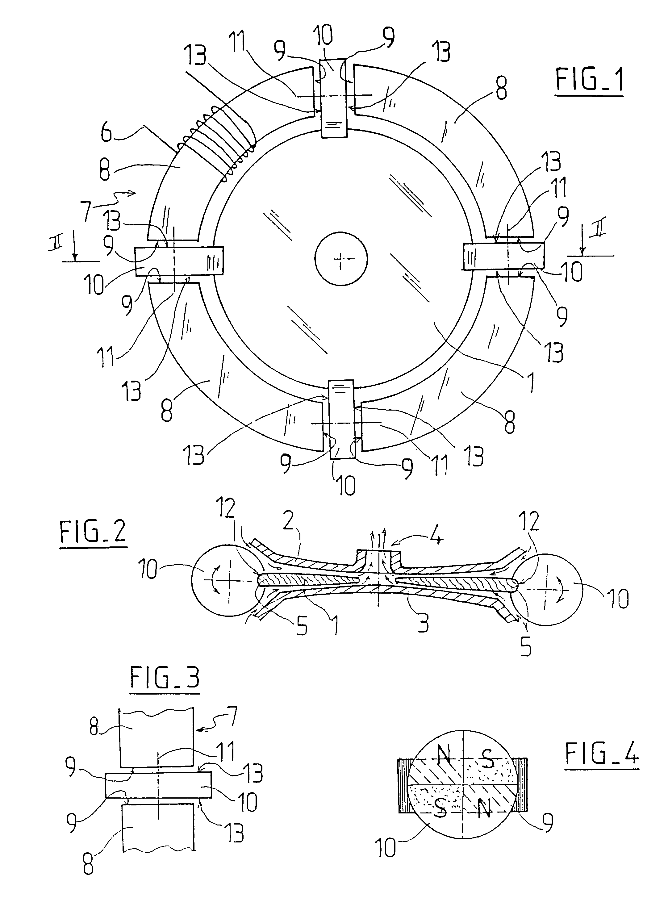
[0038]With reference to FIGS. 1 and 2, a pump in the invention comprises a circular deformable diaphragm 1, in this example made of elastomer, constrained to vibrate perpendicularly to its own plane between two rigid plates 2 and 3 as can be seen in section in FIG. 2. Vibration of the diaphragm 1 acts in known manner to suck fluid in through inlets situated at the periphery of the diaphragm 1, the fluid being forced by the vibration of the diaphragm towards a central opening in one of the plates, following the path represented by arrows in FIG. 2.

[0039]In this example, the pump is of the undulating diaphragm type. As already known from U.S. Pat. No. 6,361,284, the plates are shaped to damp a wave reflected from the diaphragm that would otherwise propagate from the central opening towards the periphery, so that the diaphragm vibrates with a traveling wave that enables energy to be transferred from the vibration of the diaphragm to the fluid in the form of kinetic energy, thus causing...

second embodiment

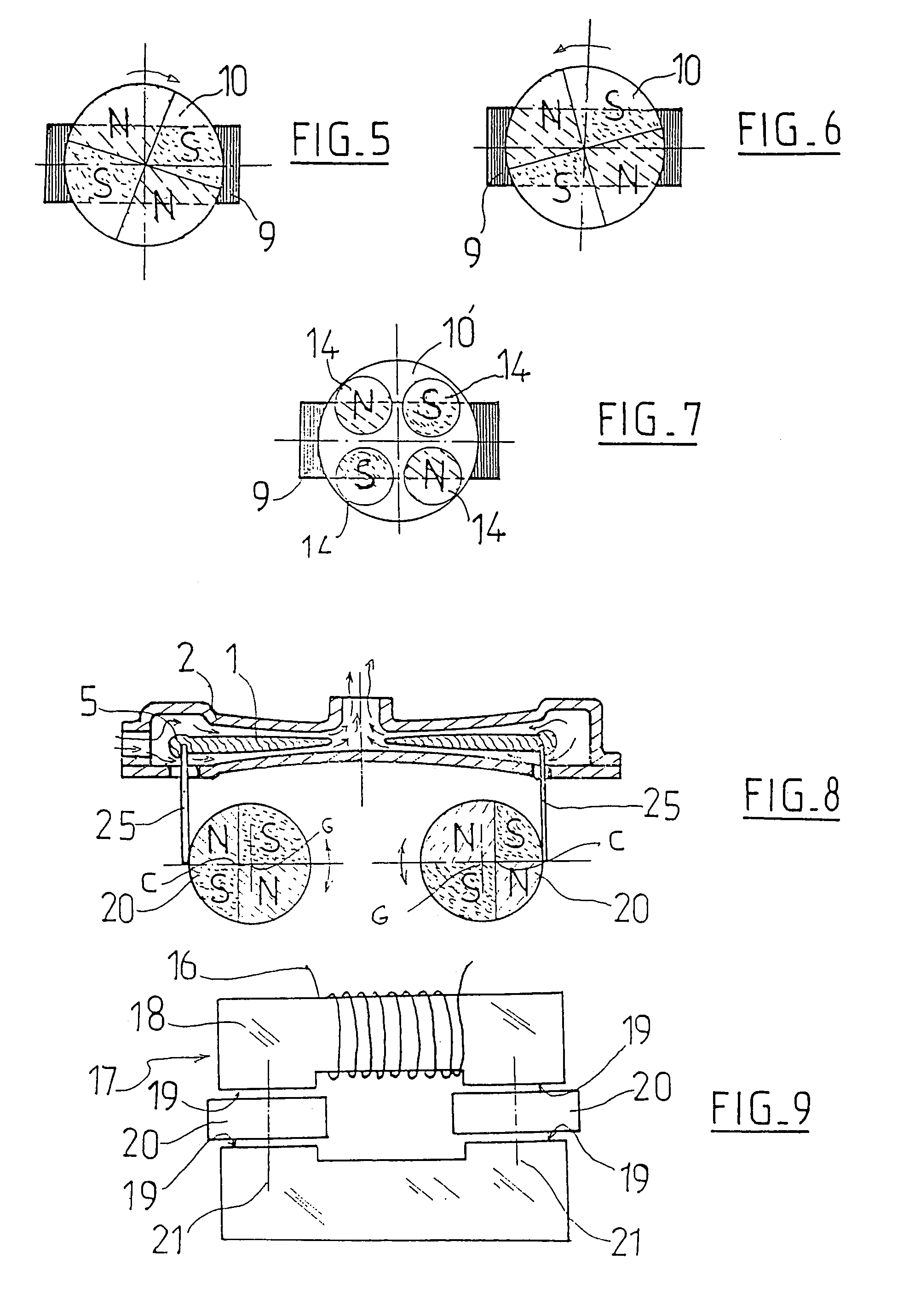
[0059]In the invention as shown in FIGS. 8 and 9, the circular vibrator diaphragm 1, still constrained to vibrate between plates 2 and 3, has its edge 5 connected to two rotors 20 by means of flexible metal blades 25 that extend from the edge 5 of the diaphragm so as to meet the peripheries of the rotors 20 tangentially. The blades 25 are secured to the rotors 20 by any suitable means, such as screw fastening or adhesive.

[0060]The rotors 20 form portions of an electromagnetic motor also comprising a coil 16 and a core 17 made up of two branches 18 (one of which passes through the coil 16). The branches 18 are terminated by active walls 19 between which the rotors 20 are disposed. The operation of this motor is entirely similar to that described with reference to FIGS. 3 to 7.

[0061]The alternating rotary motion of the rotors 20 driven by powering the coil 16 with AC causes synchronized alternating traction / compression forces to be generated in the blades 25, thereby causing the edge ...


PUM

PropertyMeasurementUnit
magnetic fluxaaaaaaaaaa
shapeaaaaaaaaaa
polaritiesaaaaaaaaaa

Abstract

An electromagnetic machine with a deformable membrane (1) includes at least one fixed part which can direct a magnetic flow interacting with at least one moveable part (12) having regions which are magnetically polarized in order to ensure that alternative displacement of the moveable part (12) corresponds to an alternative variation of the magnetic flow in the fixed part, the moveable part (12) being kinetically linked to an edge (5) of the membrane (1) such that an undulation of the membrane (1) corresponds to an alternative displacement of the moveable part (12), wherein the fixed part and moveable part (12) are arranged in such a way that the moveable part (12) can be displaced in a rotating manner.

Description

[0001]The invention relates to an electromagnetic machine with a deformable diaphragm.BACKGROUND OF THE INVENTION[0002]Machines are known having a deformable diaphragm that is driven by an electromagnetic motor comprising at least a stationary part adapted to channel an electromagnetic flux acting on at least one moving part so as to cause said moving part to move with linear alternating motion in response to alternating variation in the magnetic flux.[0003]By way of example, the machine illustrated in U.S. Pat. No. 6,361,284 comprises a diaphragm disposed between two rigid plates to undulate under the action of an electromagnetic motor in which the moving part is rigidly connected to an edge of the diaphragm so that. alternating motion of the moving part causes the diaphragm to undulate perpendicularly to its plane.[0004]It has been found that such machines emit noise, which even though not of large acoustic power, can nevertheless be troublesome in installations in which the machi...

Claims


Application Information

Patent Timeline
Patent Type & Authority Patents(United States)
IPC IPC(8): F04F7/00H01F7/00H02K7/065H02K33/16
CPCH02K33/16
Inventor DREVET, JEAN-BAPTISTE
Owner AMS R&D
Why Eureka
Try Eureka