Aerodynamic surface with improved properties

a surface and surface technology, applied in the direction of machines/engines, airflow influencers, other domestic articles, etc., can solve the problems of reducing the aerodynamic efficiency of the airframe, so as to achieve less noise and less noise, and enhance the commercial use of the latter

Inactive Publication Date: 2013-01-31
SAAB AB
View PDF2 Cites 16 Cited by
  • Summary
  • Abstract
  • Description
  • Claims
  • Application Information

AI Technical Summary

Benefits of technology

[0020]In such way an article is achieved with improved properties (being discussed in the introduction). By a unidirectional orientation of the nano filaments an efficient production of the laminate will be provided. This can be achieved by an upper ply in the form of a nano structure mat being embedded in the resin and having filaments with a random orientation in a plane such that the filaments are parallel with the plane of the upper surface. The production includes a step of introducing a resin (used as a matrix for embedding the nano filaments) into a mat of nano filaments or between separate unidirectional nano filaments. The extending—in two dimensions or in one dimension—nano filaments are thus arranged with proper extension for optimal resin fill out during the production of the laminate. The introduction of resin will have not be obstructed or hindered and the resin will fill out all air spaces between the nano filaments. Thereby the outer surface will be smooth and hard and form stable.
[0050]By achieving a less noisy aircraft, commercial use of the latter will be enhanced and due to the low fuel consumption of open rotor engines the aircraft can be made environmental-friendly.

Problems solved by technology

The materials- and manufacturing technology used today producing such surface roughment limits the aerodynamic efficiency of the airframe structures, e.g. regarding the possibility to achieve laminar air flow over a wing, fin, control surface etc.
This situation is not improved by the current standard procedure to apply a coating (paint layer) on the airframe to provide a smooth protective skin surface.
The airframe's skin surface is also prone to surface defects as a consequence of for example cure shrinkage of the polymeric material during the manufacture of the airframe and the skin surface may also be exposed to impacts and damage during flight and service.
Current technology airframe components made from aluminum, carbon fiber composites, ceramics and other materials with existing manufacturing methods suffer from a significant surface roughness, steps, gaps and waviness etc. due to insufficient manufacturing methods, and operational use (rain and sand erosion etc).
This surface layer will result in a significant surface roughness due to several contributing effects, e.g cure shrinkage of the polymeric material, uneven distribution of resin in the surface layer (resin-rich areas) and different thermal elongation of surface material.
Currently used technology also results in a surface layer having an outer surface, which is prone to surface defects during manufacturing of the component, damage due to erosion during service and other characteristics which shorten the service life of the wing surface and (primary concern) reduce the aerodynamic efficiency.
However, they are not so well suited for commercial aircrafts since they are noisy due to a high tip speed and the aerodynamic performance of the rotor blades.

Method used


Image

  • Aerodynamic surface with improved properties
  • Aerodynamic surface with improved properties
  • Aerodynamic surface with improved properties

Examples


Embodiment Construction

[0065]Hereinafter, embodiments of the present invention will be described in detail with reference to the accompanying drawings, wherein for the sake of clarity and understanding of the invention some details of no importance are deleted from the drawings. Also, the illustrative drawings show nano structures of different types, being illustrated extremely exaggerated and schematically for the understanding of the invention. The conductive nano structures are illustrated exaggerated in the figures also for the sake of understanding of the orientation and the alignment of the conductive nano filaments.

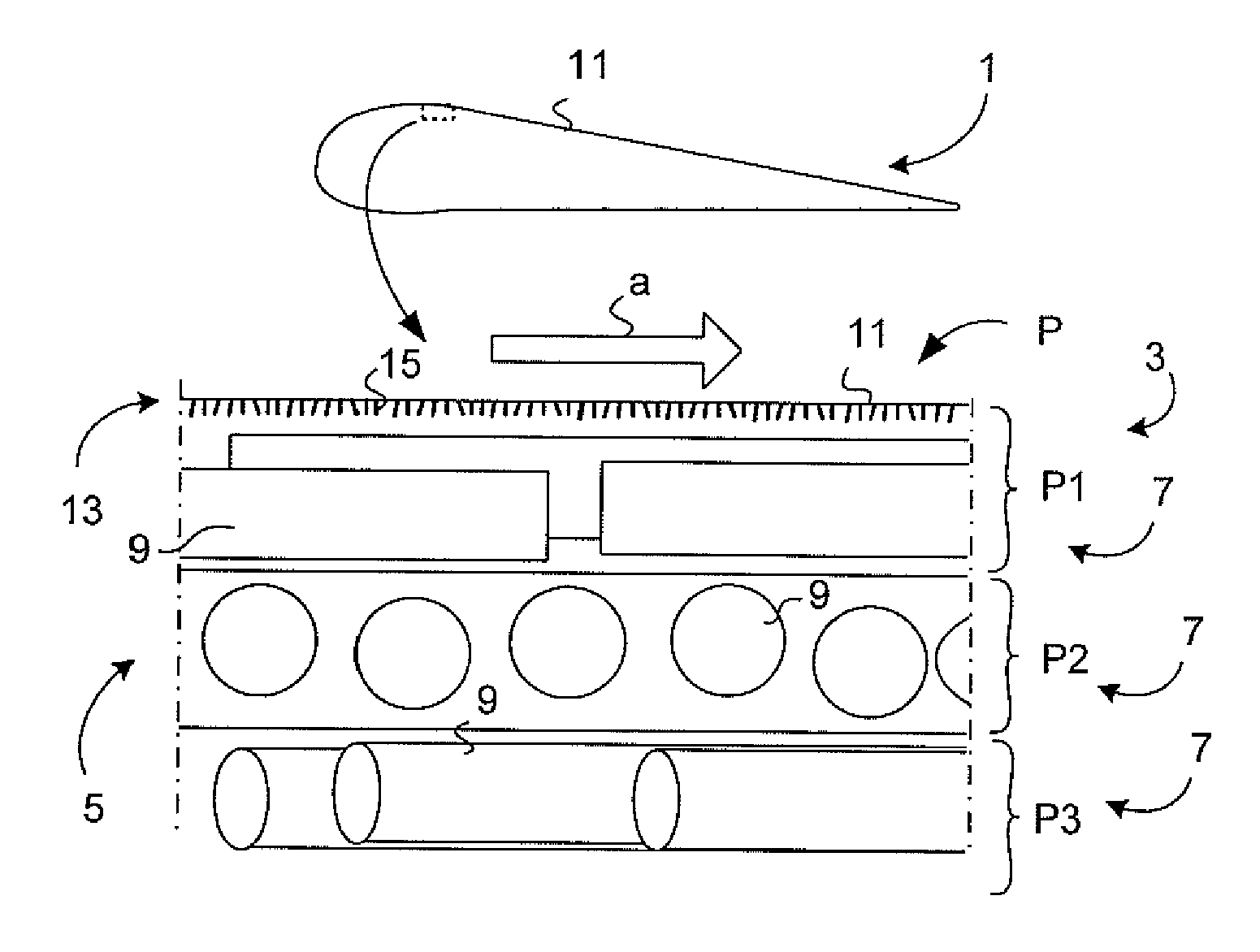
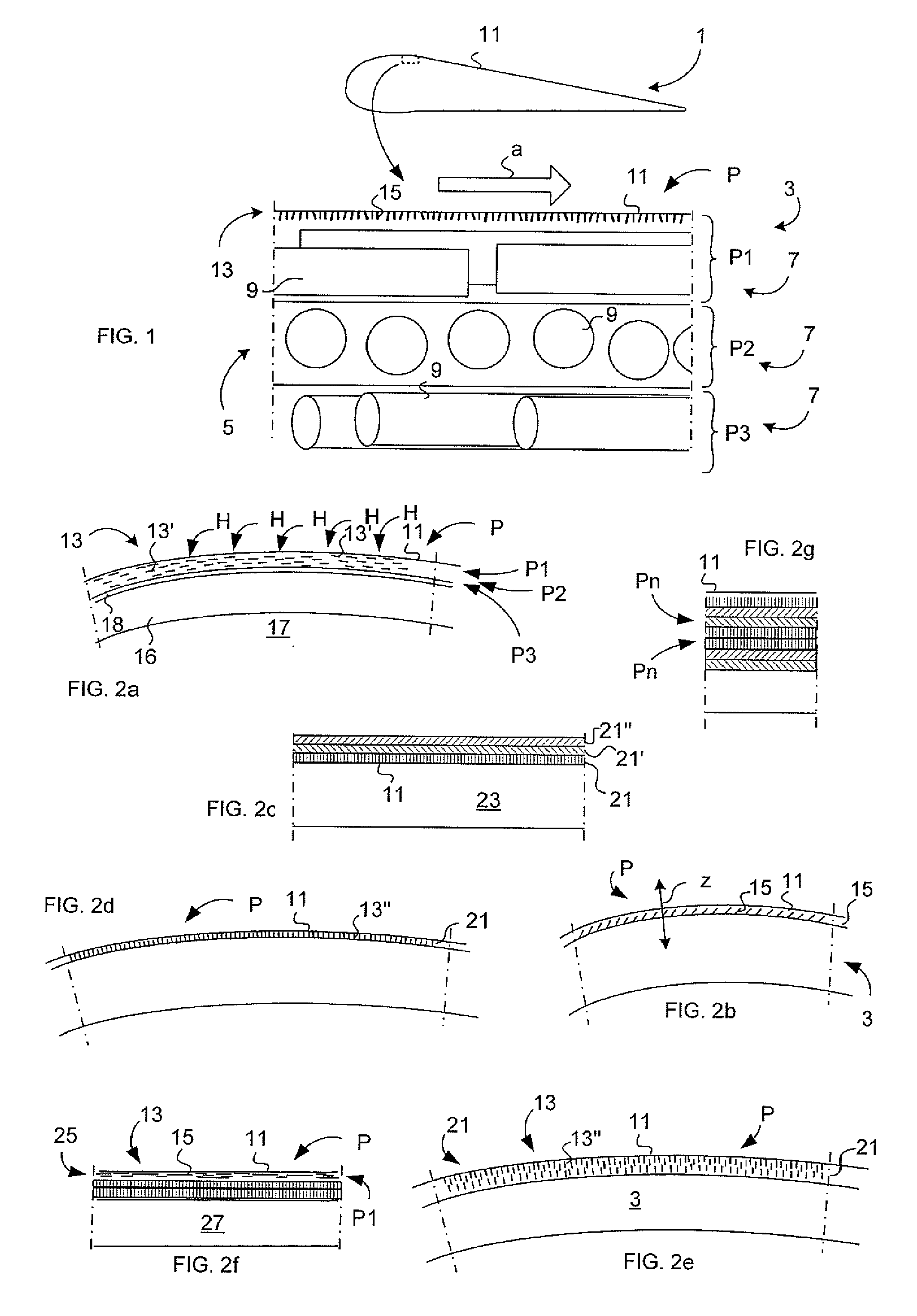
[0066]FIG. 1 illustrates a composite airframe structure 1 having an aerodynamic function. The composite airframe structure 1 corresponds in this first embodiment to a wing of an aircraft (not shown).

[0067]The wing's wing shell 3 is made of a resin matrix, which comprises a laminate 5 of plies 7. Each ply 7 comprises fibres 9 (in the present application also so called large fibres or trad...


PUM

PropertyMeasurementUnit
lengthaaaaaaaaaa
thicknessaaaaaaaaaa
diameteraaaaaaaaaa

Abstract

An article including an outer surface that serves as an aerodynamic surface when the article is subjected for an air stream. A resin matrix made of a polymeric composite laminate of at least one ply includes the outer surface. The at least one ply includes a nano structure embedded therein such that nano filaments of the nano structure in the ply essentially have the same angular orientation relative the plane of the outer surface. The outer ply is a ply of a laminate including at least two plies. Each ply includes large fibers having an orientation different from or identical to the orientation of large fibers of an adjacent ply.

Description

TECHNICAL FIELD[0001]The present invention relates to an article comprising an outer surface, which serves as an aerodynamic surface when the article's outer surface is subjected for an air stream, according to the preamble of claim 1.[0002]The invention primarily regards articles manufactured by aircraft manufacturers. The invention may also regard other fixed wing, rotary wing, propellers, aero-engine fan blades and open rotor aircraft components as well as other and aircraft components with aerodynamic requirements, wherein the component is designed with an aerodynamic surface.BACKGROUND ART[0003]Components, such as composite airframe structures of the type wing skins, fin skins, control surfaces, open rotor blades etc., having aerodynamic function, are designed and manufactured with a certain surface texture / roughness, allowable steps, gaps and waviness which affect airflow over the airframe's skin surface (i.e. the outer surface). The materials- and manufacturing technology use...

Claims


Application Information

Patent Timeline
Patent Type & Authority Applications(United States)
IPC IPC(8): B64C11/18B32B5/12B64C21/00
CPCB29C70/081B29C70/882B29K2105/167B29L2031/3076Y10T428/24132F15D1/12Y02T50/166B64C2230/26Y10T428/24124B64C21/10B29K2105/124Y02T50/10
Inventor NORDIN, PONTUSSTRINDBERG, GOTE
Owner SAAB AB
Why Eureka
Try Eureka