Method and apparatus for producing methane from carbonaceous material

a carbonaceous material and methane technology, applied in the field of energy production, can solve the problems of difficult and expensive storage of hydrogen in its free form (i.e., liquid hydrogen and compressed hydrogen), affecting the development and use of hydrogen fuels, and achieving high temperature or high pressure, efficient production of methane, and effective delivery and mixing

Inactive Publication Date: 2006-11-30
ARIZONA PUBLIC SERVICE
View PDF8 Cites 183 Cited by
  • Summary
  • Abstract
  • Description
  • Claims
  • Application Information

AI Technical Summary

Benefits of technology

[0014] Accordingly, it is an advantage of the present invention that a method and system for producing methane from a carbonaceous material are provided.
[0015] It is another advantage of the present invention that a method and system are provided that utilize hydrogen in a hydrogasification process to efficiently produce methane.
[0016] Another advantage of the present invention is that a method and system are provided for effective delivery and mixing of carbonaceous material with hydrogen without the introduction of water.
[0017] The above and other advantages of the present invention are carried out in one form by a method for producing methane from a carbonaceous material. The method calls for conveying the carbonaceous material entrained in an inert carrier fluid into a reactor. The carbonaceous material in the reactor is exposed to a swirling stream of a hydrogen gas to react the carbonaceous material with the hydrogen gas and form an exit gas that includes the methane. The exit gas is extracted from the reactor in response to the exposing operation.
[0018] The above and other advantages of the present invention are carried out in another one form by a system for producing methane from a carbonaceous material. The system includes a pulverizer for forming particulates of the carbonaceous material and a reactor in communication with the pulverizer. The reactor includes a fuel feed element having a first inlet for receiving the particulates of the carbonaceous material entrained in an inert carrier fluid from the pulverizer. The fuel feed element further has a first outlet. The reactor further includes a vortex region having a second inlet for receiving a hydrogen gas and having a second outlet. The vortex region imparts a swirling motion to the hydrogen gas to form a swirling stream of the hydrogen gas. A reaction tube is in fluid communication with each of the first and second outlets for exposing the carbonaceous material to the swirling stream of the hydrogen gas to react the carbonaceous material with the hydrogen gas and form an exit gas that includes the methane. A reactor outlet is in fluid communication with the reaction tube for extracting the exit gas from the reactor.

Problems solved by technology

However, it is envisioned that renewable sources, such as biomass,. wastes, water, wind, and sun may eventually be cost effectively harnessed to produce hydrogen.
Unfortunately, the lack of practical storage and transport methods has hindered more widespread development and use of hydrogen fuels.
Thus, the storage of hydrogen in its free form (i.e., liquid hydrogen and compressed hydrogen) is complex because it can escape from tanks and pipes more easily than conventional fuels.
To limit hydrogen escape, the fuel must be kept at extremely low temperatures or high pressures which are energy intensive and costly.
This hydrogen volatility and low temperature and / or high pressure requirements suggest that no infrastructure for storage and transport of hydrogen in its free form will be developed quickly.
An unfortunate side effect of this process is that many harmful and toxic pollutants are released into the air.
Despite its advantages, hydrogasification of carbonaceous materials has not been explored extensively for commercial purposes because the cost of hydrogen is considered prohibitive.
In addition, the efficiency for a hydrogasification process to produce methane-rich gas is not yet sufficient to be economically feasible.
These hydrogasification processes are economically inefficient, require complex and costly equipment, and call for an undesirably large quantity of water which is a commodity in arid regions.

Method used


Image

  • Method and apparatus for producing methane from carbonaceous material
  • Method and apparatus for producing methane from carbonaceous material
  • Method and apparatus for producing methane from carbonaceous material

Examples


Embodiment Construction

[0027] The present invention provides a system and apparatus for reacting a carbonaceous material with hydrogen to produce a methane-rich exit gas. The invention is discussed below with reference to the use of coal. However, it should be understood that other carbon containing materials may alternatively be utilized, such as biomass, tar sands, bitumen, oils, biogas, wastewater solids, algae, agricultural products, and wastes.

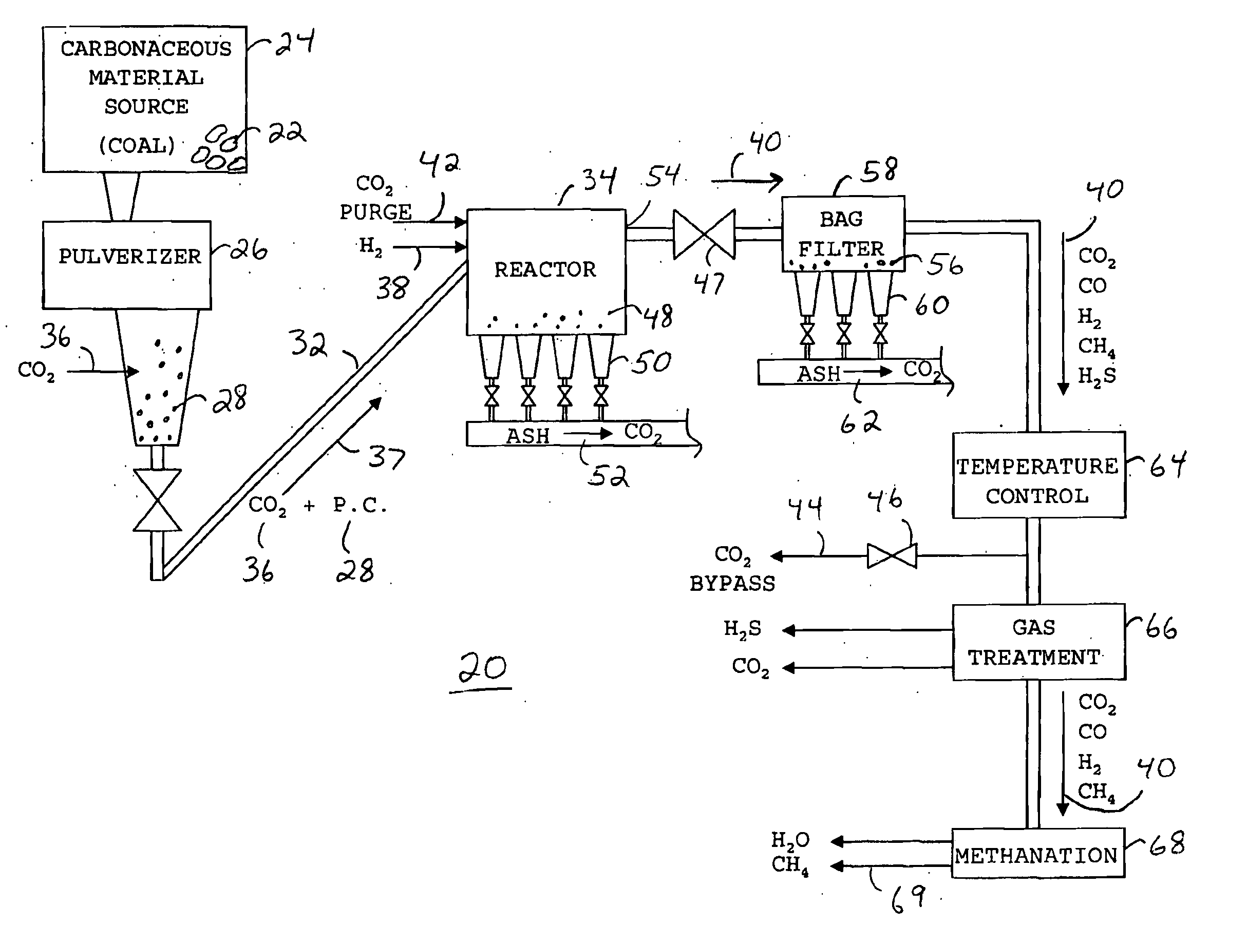
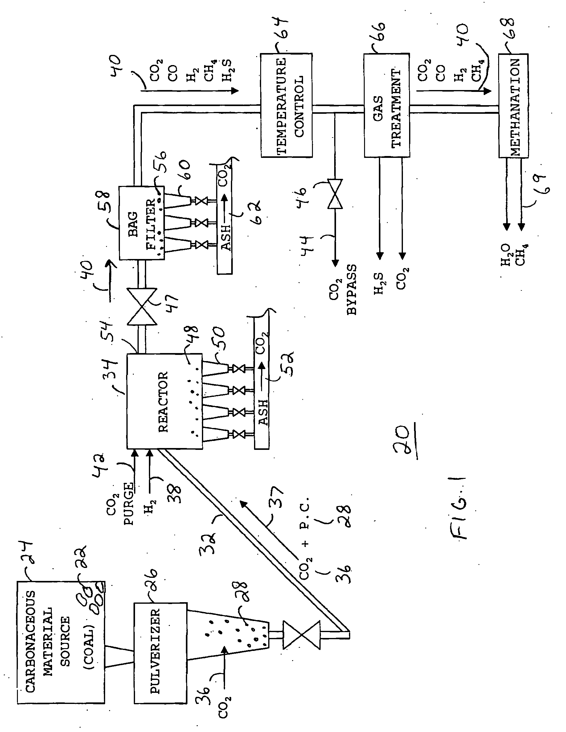
[0028]FIG. 1 shows a block diagram of a hydrogasification system 20 in accordance with a preferred embodiment of the present invention. Hydrogasification system 20 reacts carbonaceous material with hydrogen in the absence of liquid water, steam, or oil by utilizing an inert carrier fluid to convey a particulate form of the carbonaceous material.

[0029] Hydrogasification system 20 receives a carbonaceous material, in this exemplary scenario coal 22, from a source 24. Carbonaceous material source 24 may be a conventional coal bunker from which coal 22 is fed thr...


PUM

PropertyMeasurementUnit
pressureaaaaaaaaaa
heat resistanceaaaaaaaaaa
particulate sizeaaaaaaaaaa

Abstract

A method for producing methane (69) from a carbonaceous (22) material includes conveying pulverized carbonaceous material (28) entrained in an inert carrier fluid, such as carbon dioxide (36), into a reactor (34). The reactor (34) includes a vortex region (72) for receiving hydrogen gas (38) and imparting a swirling motion to the hydrogen gas (38). The pulverized carbonaceous material (28) is exposed to the swirling stream of hydrogen gas (38) in a first reaction zone (114) within the reactor (34) to form an exit gas (40) that includes methane (69). Remaining unreacted carbonaceous material (28) is further exposed to the hydrogen gas (38) in a second, low velocity, reaction zone (120). The methane rich exit gas (40) is subsequently extracted from the reactor (34) for further processing.

Description

TECHNICAL FIELD OF THE INVENTION [0001] The present invention relates to the field of energy production. More specifically, the present invention relates to a hydrogasification process for producing methane from carbonaceous material. BACKGROUND OF THE INVENTION [0002] Due to the finite supply of fossil energy sources, the global environmental damage caused by fossil fuels, increasing energy demand, and economic forces, society is becoming compelled to both diversify energy resources and utilize existing fossil fuels more effectively. [0003] One emerging energy resource that has received significant attention is hydrogen. Hydrogen is recognized by many as a key component to a clean, sustainable energy system. Some experts believe that hydrogen may eventually form the basic energy infrastructure to power future societies, replacing today's natural gas, oil, coal, and electricity infrastructures. [0004] Most of the world's current supply of hydrogen is derived from fossil fuels by, fo...

Claims


Application Information

Patent Timeline
Patent Type & Authority Applications(United States)
IPC IPC(8): C01B3/32
CPCB01J19/2405C10J2300/0906B01J2219/00763C01B3/50C01B3/586C01B2203/0445C01B2203/047C01B2203/0475C01B2203/0485C10J3/487C10J3/506C10J2300/0903C10J2300/093C10J2300/0966C10J2300/0969C10J2300/1662C10J2300/1807C10L3/08C10K1/004C10K1/005C10K1/024B01J19/26Y02P20/133
Inventor HOBBS, RAYMOND S.
Owner ARIZONA PUBLIC SERVICE
Why Eureka
Try Eureka