
Projection display apparatus using liquid cooling and air cooling

a technology of projection display and liquid cooling, which is applied in the direction of projectors, color television details, instruments, etc., can solve the problems of increasing maintenance costs, reducing the life of the product, and serious loss of functions, so as to reduce noise, reduce maintenance costs, and prolong life time

Inactive Publication Date: 2009-07-07
NEC DISPLAY SOLUTIONS LTD
View PDF29 Cites 15 Cited by
  • Summary
  • Abstract
  • Description
  • Claims
  • Application Information

AI Technical Summary

Benefits of technology

[0027]It is an object of the present invention to provide a projection display apparatus that has a long life time, is less noisy, and has a potential for a reduction in size and a higher brightness.
[0028]It is another object of the present invention to provide a method for cooling liquid crystal units so that they are less noisy and have a high cooling efficiency.

Problems solved by technology

Therefore, an orientation layer of the panel may be damaged or the polarization characteristic of the polarizing plate may be degraded when the liquid crystal panels and the polarizing plates are irradiated by light having short wavelengths for a long period, or are exposed under high temperature conditions, resulting in a serious loss of the functions.
This phenomenon may shorten the life time of the product, and raise maintenance cost due to the replacement of the unit.
Further, the quality of the combined projection image may be degraded because of the fluctuation in the properties of each color band.
However, there are the following drawbacks in the prior art techniques.
However, the increase in the number of revolutions of a fan directly causes an increase in noise, which impairs comfortable operation for users and also causes degradation in commercial value.
However, these prior arts have the following problems.
The first problem is the quality of images.
Such a liquid layer disturbs the polarization of light when the light passes through the liquid layer due to the generation of bubbles, fluctuations in the coolant density that is caused by heat transportation, and convection-induced thermal fluctuations that is caused by the fluctuations in the coolant density.
As a result, image information that passes through emitting side polarizing plate 118 is disturbed, resulting in degraded quality of projected images.
The second problem is reliability and mountability.
However, there is a risk of leakage of coolant due to failure of the pressure regulating mechanism after long use.
Additionally, the complicated sealing mechanism and pressure regulating mechanism of coolant tanks 243, 343 make the assembling process of the liquid crystal unit more difficult.

Method used


Image

  • Projection display apparatus using liquid cooling and air cooling
  • Projection display apparatus using liquid cooling and air cooling
  • Projection display apparatus using liquid cooling and air cooling

Examples


first embodiment

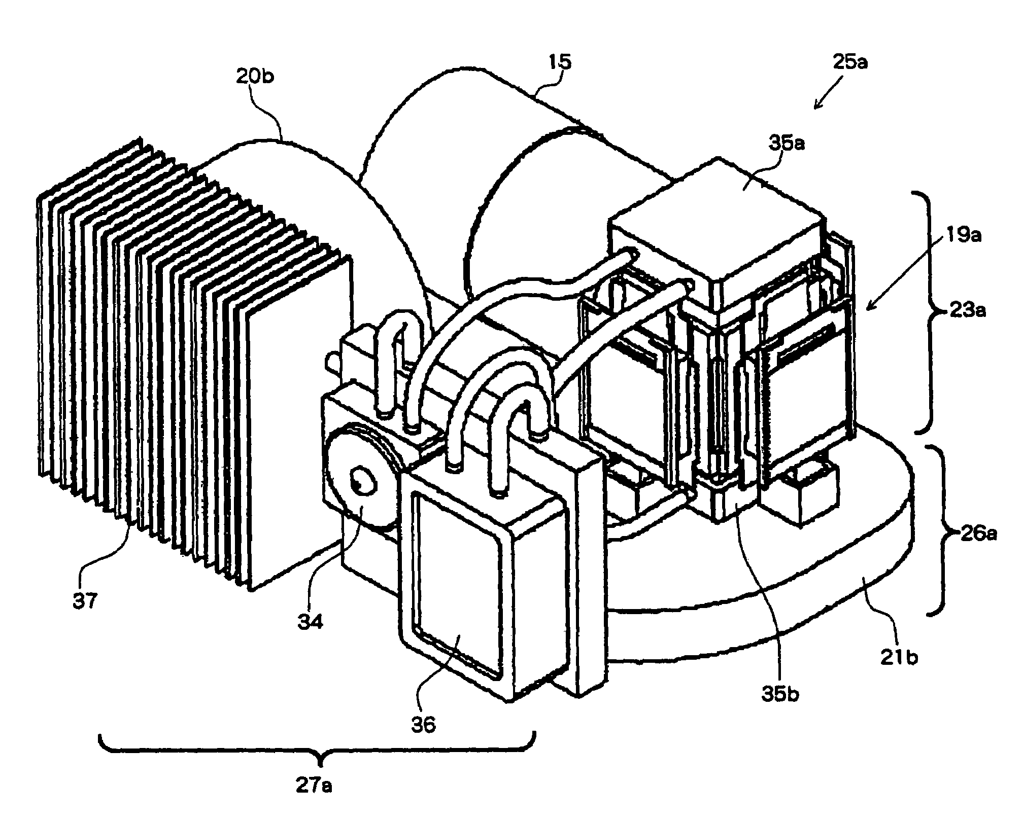
[0058]With reference to the drawings, detailed explanations are given about a mechanism for cooling liquid crystal units according to the present invention. The same reference numerals are given to the elements and the structures that have the same functions as conventional mechanisms for cooling liquid crystal units that are explained with reference to FIGS. 1 and 2. In this specification, as described above, the combination of an incident side polarizing plate, an emitting side polarizing plate, and a liquid crystal panel is called liquid crystal unit 19. The combination of three liquid crystal units, a color combining prism, and holding members is called liquid crystal unit assembly 23.

[0059]Referring to FIGS. 7 and 8, mechanism for cooling liquid crystal units 25a according to the first embodiment consists of liquid crystal unit assembly 23a, air cooling module 26a, and liquid cooling module 27a which functions as a heat exchanger.

[0060]Liquid crystal unit assembly 23a, similarl...

third embodiment

[0092]In such an arrangement of the radiator for the heat exchanger a fan is not required for heat radiation from the radiator, leading to a reduction in the cost of the overall cooling system and in noise. In addition, the size of the apparatus can be also reduced due to the reduction in the space necessary for mounting of the apparatus.

[0093]In the first, second, and third embodiments, a liquid cooling module is used as a heat exchanger. However, it is obvious that the same effect can be obtained by other types of heat exchangers, such as a heat pipe or a vapor chamber.

[0094]Finally, differences between the method for cooling liquid crystal units of prior arts, which are explained with reference to FIGS. 3 to 6, and the method according to the present invention are explained.

[0095]The first embodiment of the present invention is similar to the prior arts shown in FIGS. 3 and 4 in that heat that is generated in emitting side polarizing plates 18 is transmitted to holders 28 for co...

second embodiment

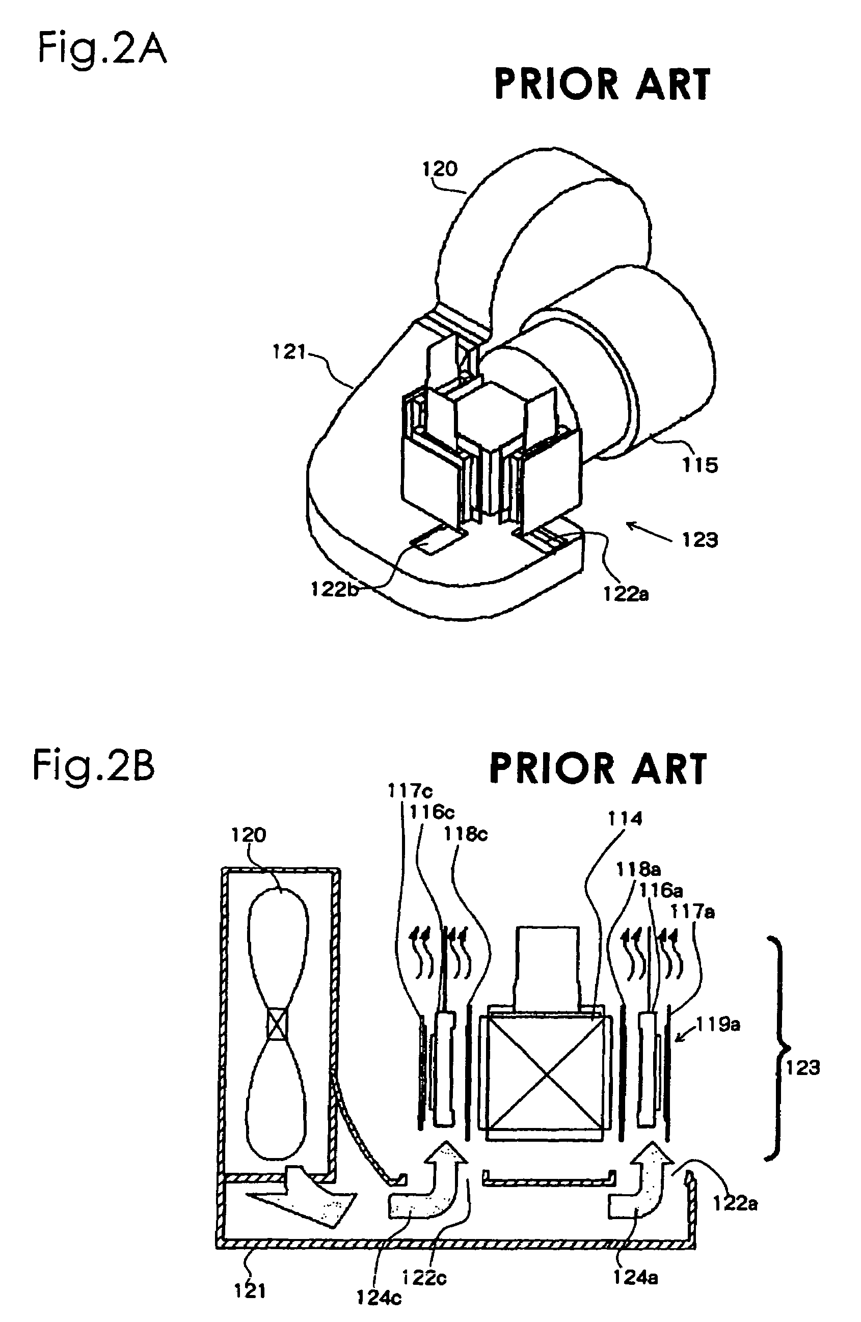
[0098]In the prior arts shown in FIGS. 3, 4, upper holder 228 for color combining prism 214 is provided with heat radiating fins 242 in order to enhance heat radiating efficiency. On the other hand, air cooling fins (heat sink) are attached to the lower holder. Further, since the fin portion is engaged in the duct of the air cooling module, which co-operates with the liquid cooling module, sufficient heat radiation by the fins can be obtained due to the sufficient level of forced convection heat transfer. The present invention is also different from the prior arts shown in FIGS. 3, 4 in these respects.

[0099]Additionally, in the first and second embodiments, the air cooling module, which co-operates with the liquid cooling module, is configured such that cooling air is concentrated on the incident side polarizing plates and the liquid crystal panels. Thus, the present invention is different from the prior arts in that the cooling margin can be easily ensured.

[0100]In the second embo...


PUM

PropertyMeasurementUnit
coloraaaaaaaaaa
translucentaaaaaaaaaa
thermal conductivityaaaaaaaaaa

Abstract

A projection display apparatus comprises a liquid crystal unit assembly which includes a liquid crystal panel, an incident side polarizing plate and an emitting side polarizing plate which are arranged on an incident side and on an emitting side of the liquid crystal panel, respectively, and a color combining prism. The apparatus further comprises a fan; a duct which is connected to the fan and which is provided with an opening for supplying cooling air, wherein the opening is arranged near the liquid crystal panel and the incident side polarizing plate; a holder for holding the emitting side polarizing plate and the color combining prism; and a heat exchanger which is connected to the holder, wherein the heat exchanger uses liquid coolant.

Description

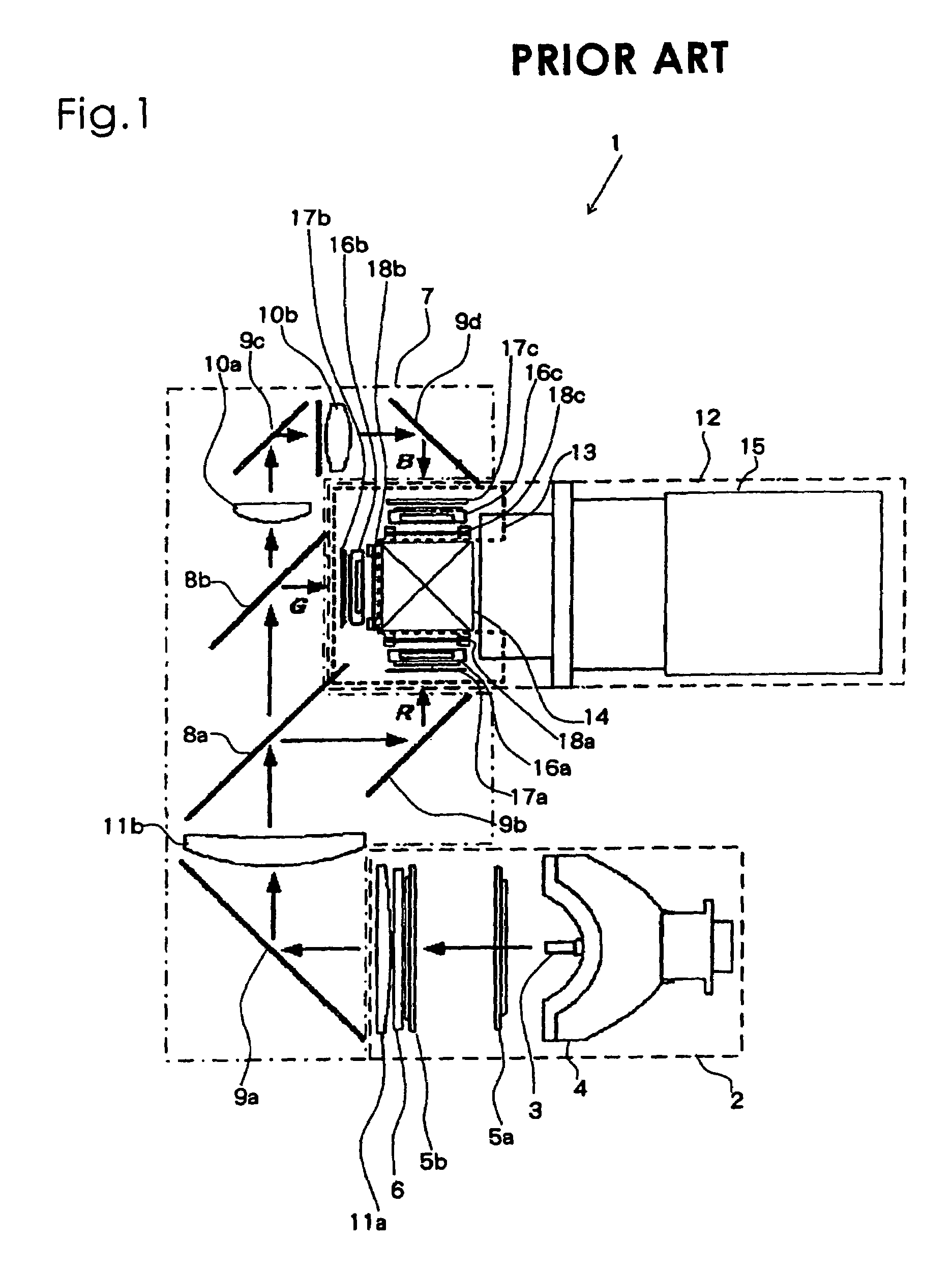
BACKGROUND OF THE INVENTION[0001]1. Field of the Invention[0002]The present invention relates to a projection display apparatus for projecting and displaying an image using a liquid crystal panel, especially to a mechanism and a method for cooling the liquid crystal panel and polarizing plates.[0003]2. Description of the Related Art[0004]In a LCD (Liquid Crystal Display) projector apparatus, which is a projection display apparatus, the quality of projected images is rapidly improving by virtue of the improved luminous efficiency of a lamp, the increased density and aperture ratio of light valves, and improvements in illuminating optical system. Therefore, LCD projectors are used in wide applications from home theater use to business presentation use.[0005]Referring to FIG. 1, explanations are given about the basic configuration of a conventional LCD projector. An LCD projector according to the present invention also has the same configuration as will be explained below. Therefore, t...

Claims


Application Information

Patent Timeline
Patent Type & Authority Patents(United States)
IPC IPC(8): G03B21/18G02F1/1333G03B21/26G02F1/1335G02F1/1347G03B21/14G03B21/16
CPCG03B21/16H04N9/3197H04N9/3144H04N9/3105
Inventor UTSUNOMIYA, MOTOYASU
Owner NEC DISPLAY SOLUTIONS LTD
Learn More