Carbon nanotube hybrid system using carbide-derived carbon, a method of making the same, an electron emitter comprising the same, and an electron emission device comprising the electron emitter

a carbon nanotube and hybrid technology, applied in the manufacture of electrode systems, electric discharge tubes/lamps, transportation and packaging, etc., can solve the problems of poor uniformity and a short life of fiber type carbon nanotube materials, and the cost of raw materials of fiber type carbon nanotubes, and achieve excellent uniformity

Inactive Publication Date: 2008-10-09
SAMSUNG SDI CO LTD
View PDF4 Cites 397 Cited by
  • Summary
  • Abstract
  • Description
  • Claims
  • Application Information

AI Technical Summary

Benefits of technology

[0014]Aspects of the present invention provide a carbon nanotube hybrid system using carbide-derived carbon that can be prepared using a less expensive method than that used to manufacture conventional carbon nanotubes and that has excellent uniformity and a long lifetime, a method of preparing the same, an electron emitter including the carbon nanotube hybrid system, and an electron emission device including the electron emitter.

Problems solved by technology

However, carbon nanotubes commonly have a fiber shape having a high field enhancement factor β, and fiber type carbon nanotube materials have many problems, such as poor uniformity and a short lifetime.
Further, when fiber type carbon nanotubes are manufactured in a paste, an ink, a slurry, or the like, problems occur during manufacturing processes compared with other particle type materials, and raw materials of the fiber type carbon nanotubes are expensive.

Method used


Image

  • Carbon nanotube hybrid system using carbide-derived carbon, a method of making the same, an electron emitter comprising the same, and an electron emission device comprising the electron emitter
  • Carbon nanotube hybrid system using carbide-derived carbon, a method of making the same, an electron emitter comprising the same, and an electron emission device comprising the electron emitter
  • Carbon nanotube hybrid system using carbide-derived carbon, a method of making the same, an electron emitter comprising the same, and an electron emission device comprising the electron emitter

Examples


example 1

Preparation of Carbon Nanotube Hybrid System

[0079]100 g of α-SiC having an average diameter of 0.7 μm as a carbon precursor was maintained in a high temperature furnace composed of a graphite reaction chamber, a transformer, and the like. 0.5 L of Cl2 gas was applied to the high temperature furnace at 1000° C. per minute for 7 hours. Then, 30 g of carbide-derived carbon was prepared by extracting the Si from the carbon precursor.

[0080]The carbide-derived carbon was analyzed using Raman peak analysis, X-ray diffraction, and an electron microscope. As a result, the IG / ID ratio was about 0.5 to 1. A weak peak of a graphite (002) surface could be seen at 2θ=25°, and the electron diffraction pattern was a halo-pattern of amorphous carbon. Further, the specific surface area of the carbide-derived carbon after synthesizing the carbide-derived carbon was 1000 to 1100 m2 / g.

[0081]20 g of the carbide-derived carbon was mixed with 2 g of iron (III) nitrate (Fe(NO3)3) in an ethanol solution, the...

example 2

Preparation of Carbon Nanotube Hybrid System

[0082]9.5 g of carbide-derived carbon was prepared in the same manner as in Example 1 except that 100 g of NiC having an average diameter of 3 μm was used as a starting carbide compound and was heat treated at 500° C. for 2 hours. The carbide-derived carbon was analyzed using Raman peak analysis. The IG / ID ratio was about 1 to 1.3. A wide single peak of a graphite (002) surface could be seen at 2θ=25° using the X-ray diffraction. In addition, the specific surface area of the carbide-derived carbon after synthesizing the carbide-derived carbon was 1200 m2 / g.

[0083]The amount of nickel in the carbide-derived carbon was 10.5 parts by weight based on 100 parts by weight of the total amount of the carbide-derived carbon and nickel.

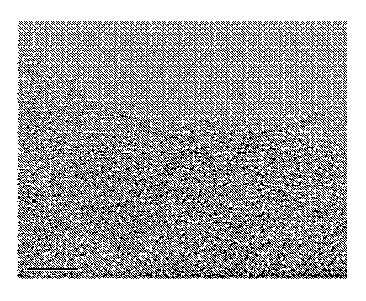
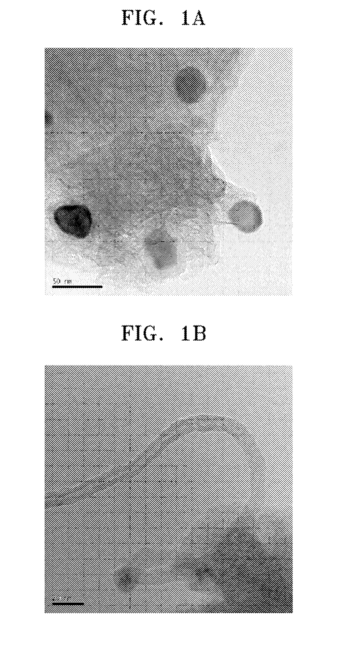
[0084]The resultant was purged with air to completely remove Cl2 gas in the furnace, and ethylene gas was supplied to the furnace and reacted at 900° C. to prepare a carbon nanotube hybrid system in which carbon nanotu...

example 3

Preparation of Carbon Nanotube Hybrid System

[0085]13 g of carbide-derived carbon was prepared in the same manner as in Example 1 except that 100 g of ZrC having an average diameter of 5 μm was used as a starting carbide compound and was heat treated at 600° C. for 5 hours. The carbide-derived carbon was analyzed using Raman peak analysis. The IG / ID ratio was about 1 to 1.3. A wide single peak of a graphite (002) surface could be seen at 2θ=25° using the X-ray diffraction. In addition, the specific surface area of the carbide-derived carbon after synthesizing the carbide-derived carbon was 1200 m2 / g.

[0086]A carbon nanotube hybrid system was prepared in the same manner as in Example 1 except that the carbide-derived carbon of Example 3 was used.


PUM

PropertyMeasurementUnit
particle sizeaaaaaaaaaa
particle size distributionaaaaaaaaaa
diameteraaaaaaaaaa

Abstract

A carbon nanotube hybrid system includes: a carbide-derived carbon prepared by reacting a carbide compound and a halogen group containing gas to extract elements of the carbide compound except carbons; metals supported on the carbide-derived carbon or remaining in the carbide-derived carbon; and carbon sources from which carbon nanotubes are grown from the carbide-derived carbon. A method of preparing the carbon nanotube hybrid system includes preparing the carbide-derived carbon, extracting elements therefrom, and growing carbon nanotubes from the carbide-derived carbon. The carbon nanotube hybrid system has excellent uniformity and a long lifetime. An electron emitter having improved electron emitting properties can be inexpensively prepared using the carbon nanotube hybrid system compared to conventional carbon nanotubes. An electron emission device having excellent electron emitting properties can be prepared using the electron emitter.

Description

CROSS-REFERENCE TO RELATED APPLICATION[0001]This application claims the benefit of Korean Application No. 2007-33358, filed on Apr. 4, 2007, in the Korean Intellectual Property Office, the disclosure of which is incorporated herein by reference.BACKGROUND OF THE INVENTION[0002]1. Field of the Invention[0003]Aspects of the present invention relate to a carbon nanotube hybrid system using carbide-derived carbon, an electron emitter including the same, and an electron emission device including the electron emitter, and more particularly, to a carbon nanotube hybrid system that can be prepared using a less expensive method than that used to manufacture conventional carbon nanotubes and that has excellent uniformity and a long lifetime, an electron emitter including the same, and an electron emission device including the electron emitter.[0004]2. Description of the Related Art[0005]In general, electron emission devices can be classified into electron emission devices using hot cathodes a...

Claims


Application Information

Patent Timeline
Patent Type & Authority Applications(United States)
IPC IPC(8): B32B9/00D01F9/12
CPCB82Y30/00B82Y40/00C01B31/0233C01B2202/02Y10T428/30H01J9/025H01J2201/30469Y10S977/742H01J1/304C01B32/162B82B3/00
Inventor KIM, YOON-JINKIM, JAE-MYUNGMOON, HEE-SUNG
Owner SAMSUNG SDI CO LTD
Why Eureka
Try Eureka