Housing for hand held scanner

a scanner and hand-held technology, applied in the field of hand-held optical readers or scanners, can solve the problems of difficult modification and high cost of customizing systems for specific applications, and achieve the effect of improving ergonomic design

Inactive Publication Date: 2008-02-05
SYMBOL TECH LLC
View PDF8 Cites 3 Cited by
  • Summary
  • Abstract
  • Description
  • Claims
  • Application Information

AI Technical Summary

Benefits of technology

[0016]It is a further object of the invention to provide a hand-held optical reader capable of being used quickly and efficiently and with minimum discomfort to the user.
[0028]The main body may include a visual display, for example an LCD display. The main body may also comprise a keypad. The modules may comprise an image capture module, a laser scanner module and / or a multi-media module. The modules preferably include digital signal processing sub-systems which may be of a single design and programmable as appropriate. The modules may comprise pre-processors or preprocessing information prior to transfer to the main body to reduce the burden on the processor in the main body. The module may be movably mounted on or relative to the main body, and in particular to the display on the main body for example it may be hinged pivotally or rotatably mounted.

Problems solved by technology

The manufacture of a customized system for a specific application is expensive and difficult to modify if it is subsequently desired to incorporate further data capture options than those originally provided in the customized device.

Method used


Image

  • Housing for hand held scanner
  • Housing for hand held scanner
  • Housing for hand held scanner

Examples


Embodiment Construction

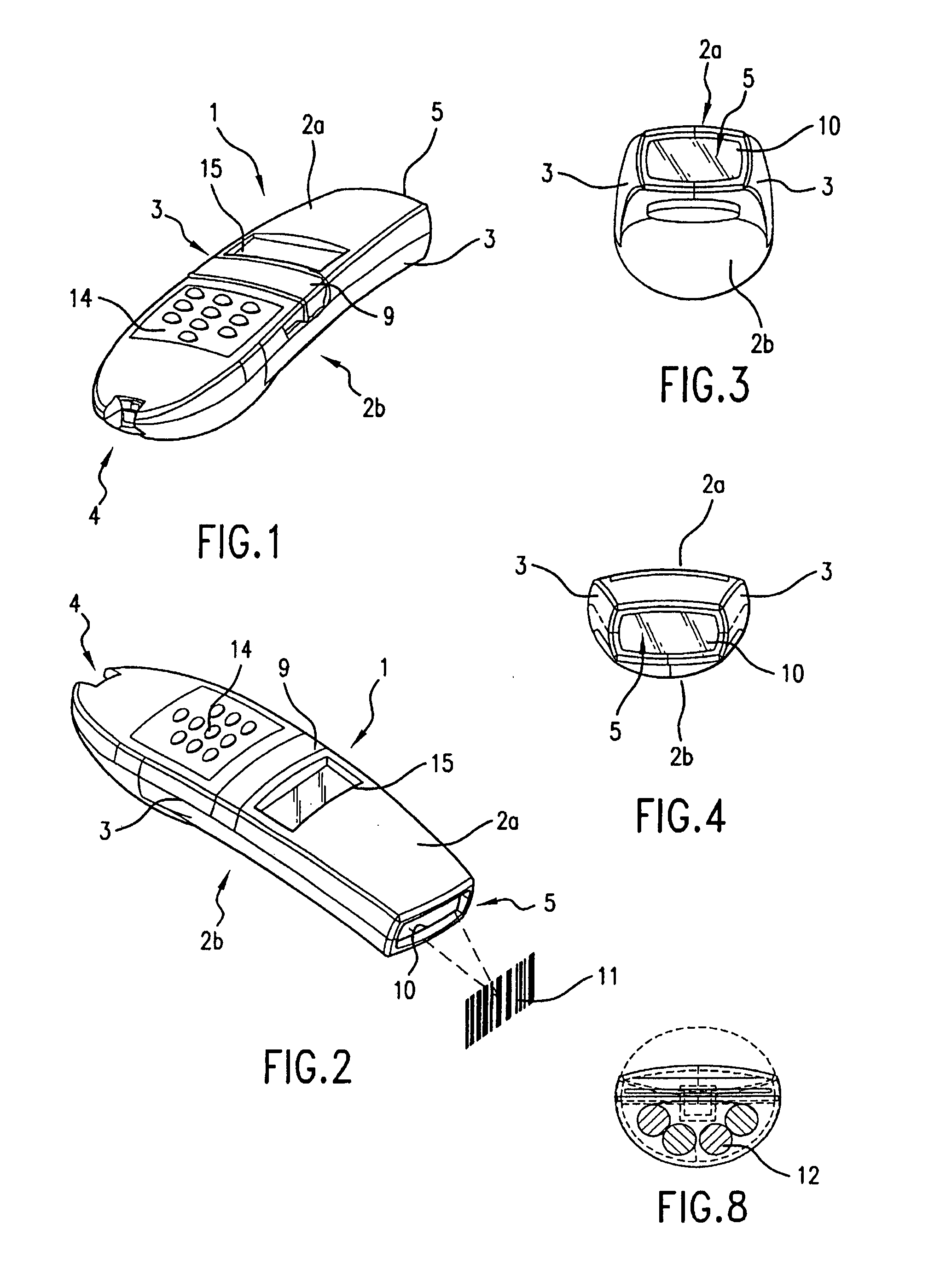
[0066]Referring now to FIGS. 1 to 4, the optical reader has a rear end 4 and a generally planar front end 5, an upper face 2a and opposed to that a lower face 2b.

[0067]Referring to FIGS. 1 to 4 in more detail, the optical reader includes a generally bar-shaped elongate housing indicated generally by the reference numeral 1, having two generally opposed long broad upper and lower faces 2a, 2b (see also FIG. 7), two generally opposed long, shallow side faces 3, a rear end 4 and a front end 5 (see also FIG. 6).

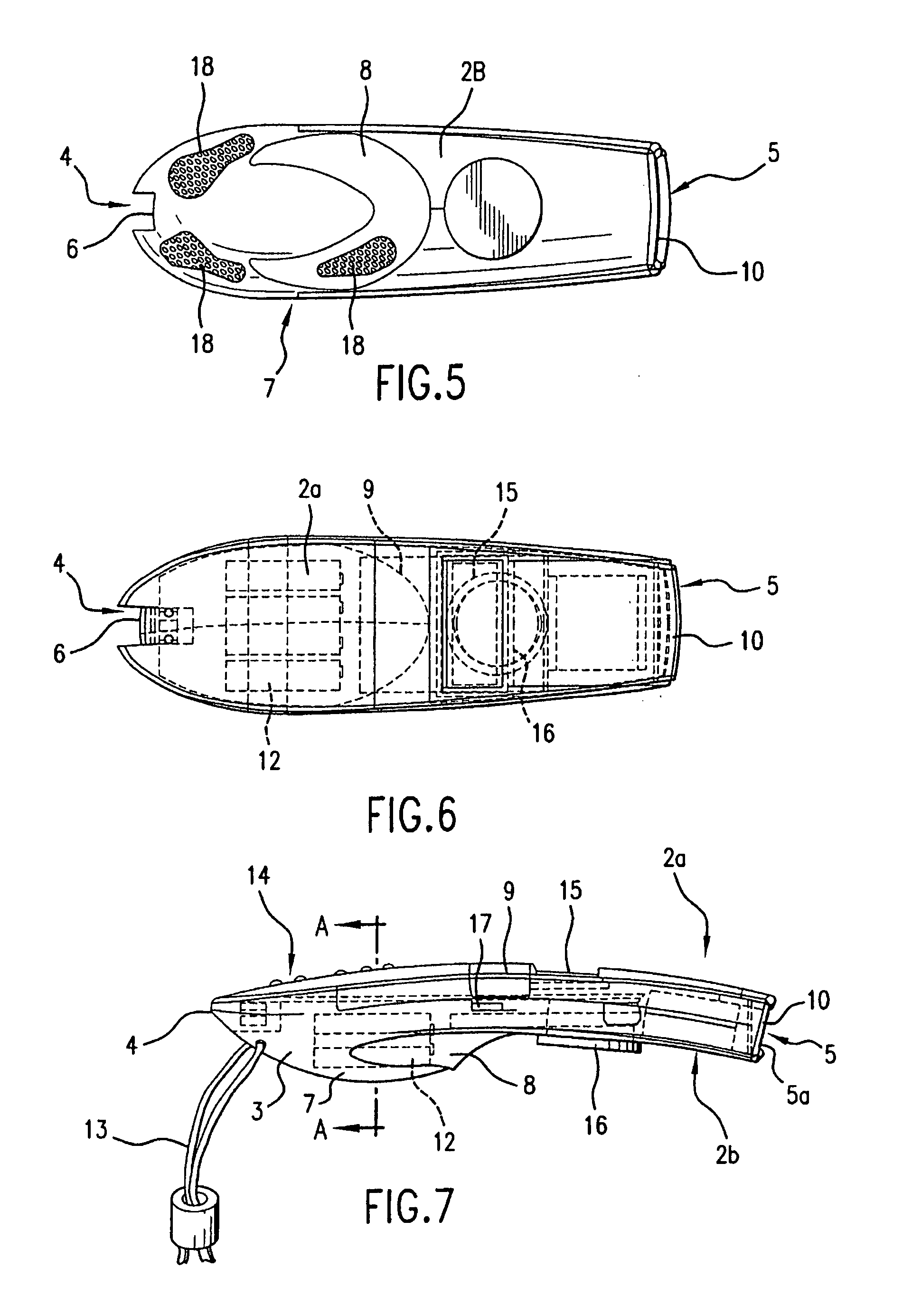
[0068]As can be seen from FIGS. 5 and 6, the upper and lower faces 2a, 2b of the reader comprise side edges having substantially straight front portions tapering inwardly towards the front end 5 which is of a convex shape having a large radius of curvature. The rear portions of the side edges curve inwardly and meet so that the rear end 4 of the housing is generally elliptical in shape when viewed from above. The rear end is interrupted by a recessed connector 6 which is describ...


PUM


Abstract

A housing for a hand-held scanner has an upper surface having a front portion and a rear portion, a lower surface having a front portion and a rear portion, side surfaces between the upper and lower surfaces and a first groove in the lower surface between the front portion and rear portion for receiving a finger of a hand holding the housing during use. The side surfaces have second grooves therein extending from the first groove towards the rear portion of the upper and lower surfaces a sufficient distance to receive the tips of at least two fingers of a hand holding the housing during use.

Description

CROSS-REFERNCE TO RELATED APPLICATIONS[0001]This application is a continuation of U.S. patent application Ser. No. 10 / 303,667 filed Nov. 25, 2002, now abandoned, which is a continuation of U.S. patent application Ser. No. 09 / 538,812, filed Mar. 30, 2000, now U.S. Pat. No. 6,543,695, which is a continuation-in-part of U.S. patent application Ser. No. 08 / 916,605, filed Aug. 22, 1997, now abandoned, which is a continuation of U.S. patent application Ser. No. 08,691,263 filed Aug. 2, 1996, now abandoned. U.S. patent application Ser. No. 09 / 538,812 is also a continuation-in-part of U.S. Pat. applications Nos. 29 / 116,604, now U.S. Pat. No. D431,562, 29 / 116,597, now U.S. Pat. No. D430,159, 29 / 116,589, now U.S. Pat. No. D430,158 and 29 / 116,606, now U.S. Pat. No. D436,104, all filed Jan. 6, 2000. U.S. patent application Ser. No. 09 / 359,019, filed Apr. 22, 1999, now abandoned, is also a continuation of U.S. patent application Ser. No. 08 / 916,605.BACKGROUND OF THE INVENTION[0002]1. Field of th...

Claims


Application Information

Patent Timeline
Patent Type & Authority Patents(United States)
IPC IPC(8): G06K7/10G06F1/16G06F1/18G06F3/033G06F17/30H04L12/28H04L12/56H04L29/12
CPCG06F1/1616G06F1/1626G06F1/1632G06F1/1656G06F1/181G06F3/03545G06F17/30047G06F17/30879H04L29/12009H04L61/00H04W88/02G06F16/434G06F16/9554
Inventor HAMILTON, ALISTAIRBHATIA, SUDHIRSWIFT, PHILIPJWO, CHINH-HUNG
Owner SYMBOL TECH LLC
Why Eureka
Try Eureka