Illumination apparatus for an optical occupant monitoring system in a vehicle

a monitoring system and optical occupant technology, applied in lighting and heating apparatus, pedestrian/occupant safety arrangements, instruments, etc., can solve the problems of increased bulkiness of mirrors, safety hazards, and distraction for drivers, and achieve the effect of reducing the cost of additional components

Inactive Publication Date: 2008-02-26
DELPHI TECH INC
View PDF6 Cites 1 Cited by
  • Summary
  • Abstract
  • Description
  • Claims
  • Application Information

AI Technical Summary

Benefits of technology

[0011]An advantage of the present invention is that the illumination device does not occupy additional space within the passenger compartment of the vehicle.
[0012]Another advantage is that the illumination device does not obstruct the view of the driver.
[0013]Yet another advantage is that the illumination device may be used in conjunction with conventional rearview mirror mounting features and structures. Thus, the illumination device requires minimal additional component packaging costs.
[0014]A further advantage is that the illumination device may provide uniform illumination of both the driver and front passenger areas.

Problems solved by technology

Illumination by visible light would be distracting to the driver.
One of the challenges involved with using artificial illumination is the integration and alignment of the physical components.
Packages that “hang” off the bottom of the mirror increase the bulkiness of the mirror and pose a safety hazard by partially obstructing the driver's view of the forward scene.

Method used


Image

  • Illumination apparatus for an optical occupant monitoring system in a vehicle
  • Illumination apparatus for an optical occupant monitoring system in a vehicle
  • Illumination apparatus for an optical occupant monitoring system in a vehicle

Examples


Embodiment Construction

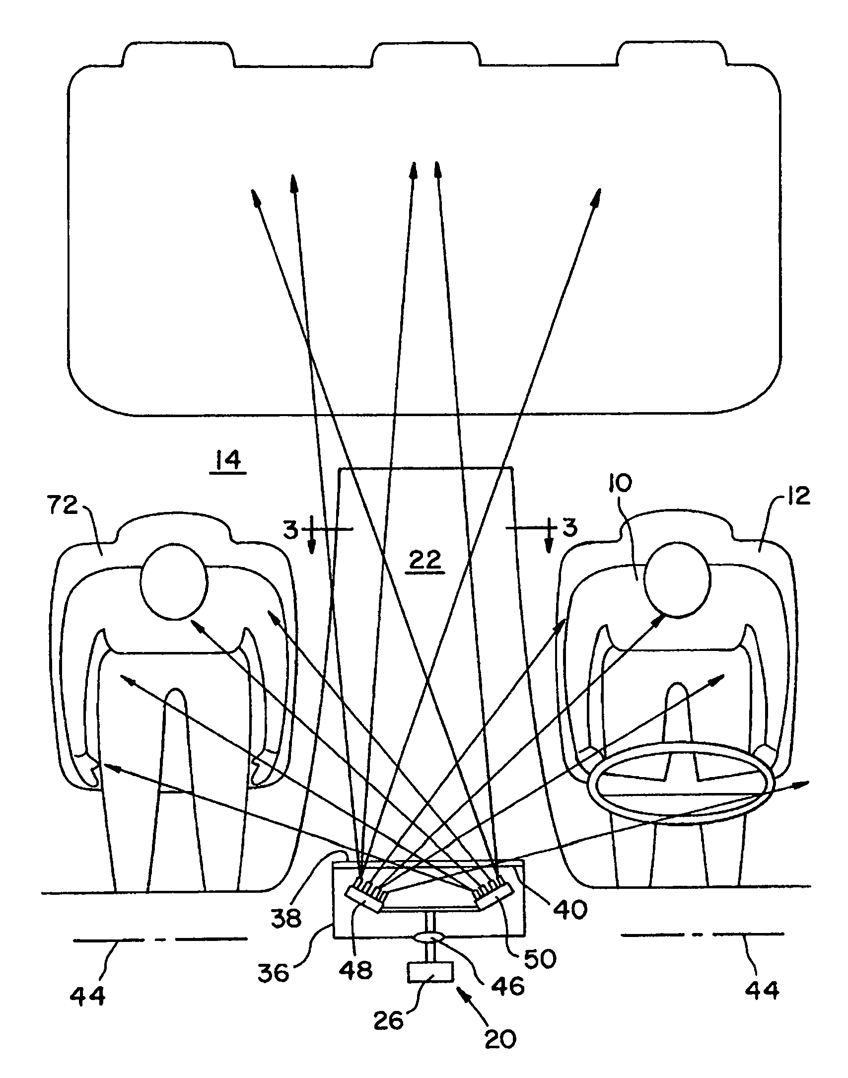
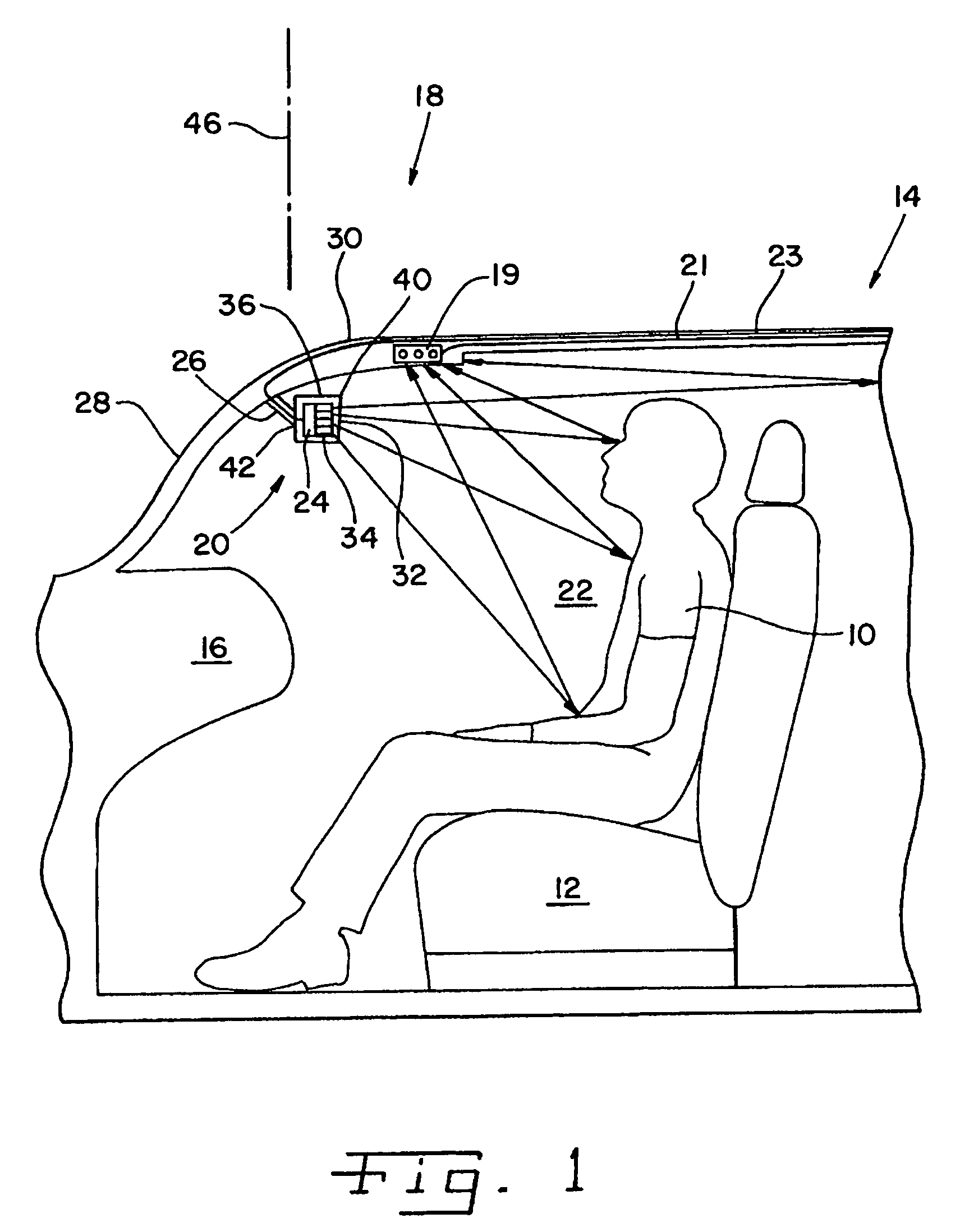
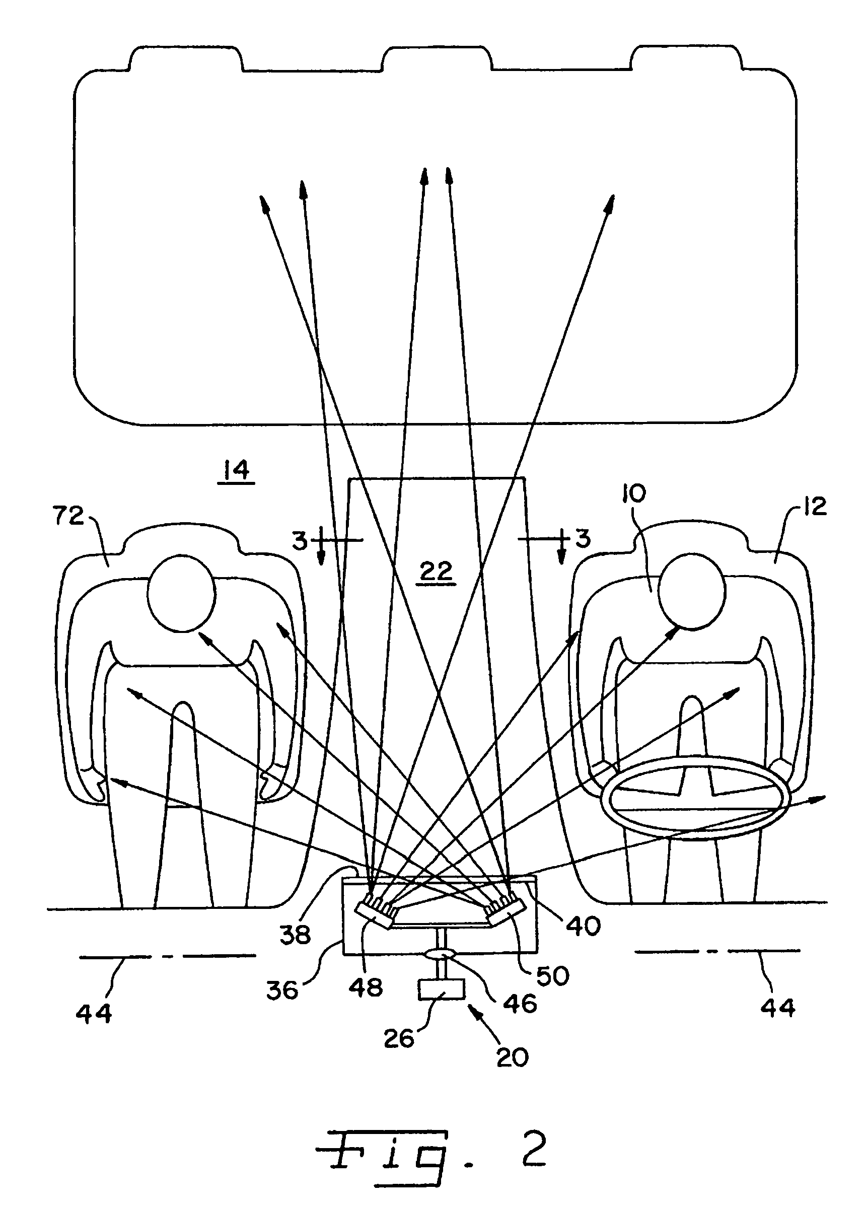
[0022]Referring now to the drawings, and particularly to FIG. 1, there is shown a person 10 seated on a driver's seat 12 of a vehicle 14. As shown, person 10 is properly seated on seat 12, with his hips and back placed against the back of the seat, and with the seat set at a safe distance spaced from dashboard 16 of vehicle 14.

[0023]An occupant monitoring arrangement 18 is provided in vehicle 14 for performing occupant monitoring functions such as needed in systems that monitor the direction of a driver's gaze, and / or systems that monitor the frequency of a driver's blinking in order to detect when the driver is falling asleep. Occupant monitoring arrangement 18 may also be provided in vehicle 14 for performing other occupant monitoring functions such as driver identification, occupant classification, vehicle security, and occupant position detection.

[0024]Arrangement 18 includes an illumination apparatus 20 for illuminating a passenger compartment 22 of vehicle 14. Illumination app...


PUM


Abstract

An optical occupant monitoring arrangement for a vehicle includes a mounting device attached to a fixed structure of the vehicle. A frame is pivotably attached to the mounting device. A rearview mirror is retained within the frame. An optical energy source is fixedly attached to the mounting device and emits optical energy through the mirror into a passenger compartment of the vehicle. An optical energy receiver receives the optical energy emitted by the optical energy source after the optical energy has been reflected within the passenger compartment of the vehicle.

Description

TECHNICAL BACKGROUND[0001]This invention relates generally to automotive optical sensing systems, and, more particularly, to a novel illumination device for an automotive optical sensing system.BACKGROUND OF THE INVENTION[0002]Automotive optical sensing systems are used to monitor the occupants within a passenger compartment of a vehicle. Such optical sensing systems may be used for driver gaze and drowsiness monitoring, driver identification, occupant classification, occupant position detection, and vehicle security. Further, such optical sensing systems may be used in other types of vision-based safety, convenience, and driver aid systems that are being introduced into vehicles.[0003]The optical sensing system must function in a wide variety of ambient lighting conditions, including at night when the passenger compartment is relatively dark. Thus, the performance of the optical sensing system may depend upon, or at least benefit from, artificial or active illumination from a light...

Claims


Application Information

Patent Timeline
Patent Type & Authority Patents(United States)
IPC IPC(8): B60Q1/26
CPCB60Q3/023B60R21/01534B60R2011/0028B60R1/1207B60Q3/258
Inventor SCHARENBROCH, GREGORY K.HARTER, JR., JOSEPH E.
Owner DELPHI TECH INC
Why Eureka
Try Eureka