Single-piece top surface display layer and integrated front cover for an electronic device

a technology of electronic devices and display layers, applied in the direction of static indicating devices, electric apparatus casings/cabinets/drawers, instruments, etc., can solve the problems of reducing the sensitivity to external mechanical pressure required to activate the digitizer mechanism, and affecting the operation of the digitizer. , to achieve the effect of reducing the possibility of damage to electronic components and reducing the parallax

Inactive Publication Date: 2008-03-25
QUALCOMM INC
View PDF25 Cites 83 Cited by
  • Summary
  • Abstract
  • Description
  • Claims
  • Application Information

AI Technical Summary

Benefits of technology

[0014]It would be advantageous, then, to provide a flat bezel-free display interface. Such an interface would reduce the possibility of damage to electronic components from dust or water. It would also be advantageous to provide a display interface which reduces the parallax effect and passes more light from the display to the viewer. The present invention provides a solution to meet the above needs.
[0015]Accordingly, embodiments of the present invention solve the problems of parallax and reduced display quality seen in today's touch screen displays. Embodiments of the present invention also eliminate the need for the bezel usually seen with touch screen displays. The optical properties of the display are improved because the layers required for the conventional analog resistive touch screens are eliminated. Embodiments of the present invention enable thinner construction. They improve the optical performance of the display including power efficiency, contrast, and brightness. These and other advantages of the present invention and others not specifically recited above will be described in more detail herein.
[0017]In another embodiment, the cover is transparent, rigid, and extends around the display to directly contact the pressure activated sensors. The sensors may be located in front of the display, behind it, or may be located in the housing. The display is coupled with the cover. When pressure is applied to the cover, the cover deflects and activates the sensors. In both embodiments, an accelerometer can be used for thresholding to identify valid input events. This display minimizes the problems of parallax and reduced display brightness because the display is seen without the intervening layer of the touch screen mechanism.

Problems solved by technology

The problem here is the reduction in the sensitivity to the external mechanical pressure required to activate the digitizer mechanism.
In addition, the added protective film may increase overall opacity which makes it more difficult to view any display element housed within.
These step-down corners add thickness to the assembly, are dust and moisture collectors, are difficult to clean, and frequently do not seal properly.
One problem with the bezel design is that maintaining a moisture and dust-free environment for the touch screen mechanism is difficult.
Such an assembly often does not provide a satisfactory moisture and dust proof enclosure.
An additional problem involves the complexity and cost of assembly.
Yet another problem involves the overall thickness of the device.
The bezel design adds unwanted thickness to the display components.
Another drawback is that, because of the amount of space between the touch surface of the touch screen and display screen, there is what is commonly referred to as the parallax effect.
An additional drawback is that the amount of light that comes from the display screen through the touch screen to be viewed by the user is only about 80% of the available light.
This reduces the overall contrast, clarity, and quality of the display as seen by the user.

Method used


Image

  • Single-piece top surface display layer and integrated front cover for an electronic device
  • Single-piece top surface display layer and integrated front cover for an electronic device
  • Single-piece top surface display layer and integrated front cover for an electronic device

Examples


Embodiment Construction

[0027]A single-piece top surface display and integrated front cover for an electronic device is described. While numerous details are set forth in order to provide a thorough understanding of the present invention, it should be understood that it is not intended to limit the invention to this particular embodiment alone. On the contrary, the invention is intended to cover alternatives, modifications and equivalents, which may be included within the spirit and scope of the invention as defined by the appended claims. However, it will be obvious to one of ordinary skill in the art that the present invention may be practiced without these specific details. In other instances, well-known methods, procedures, components, and circuits have not been described in detail so as not to unnecessarily obscure aspects of the present invention.

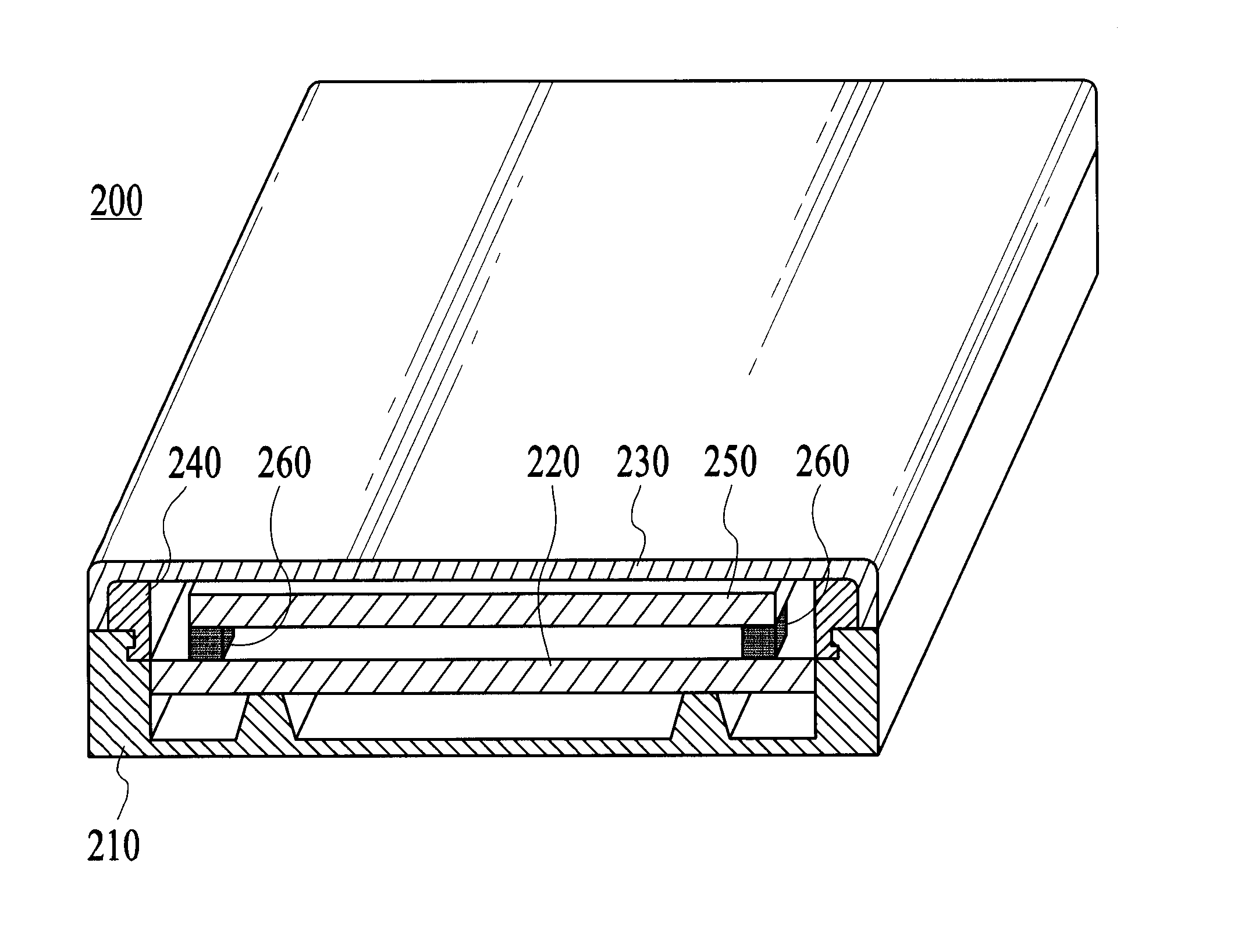
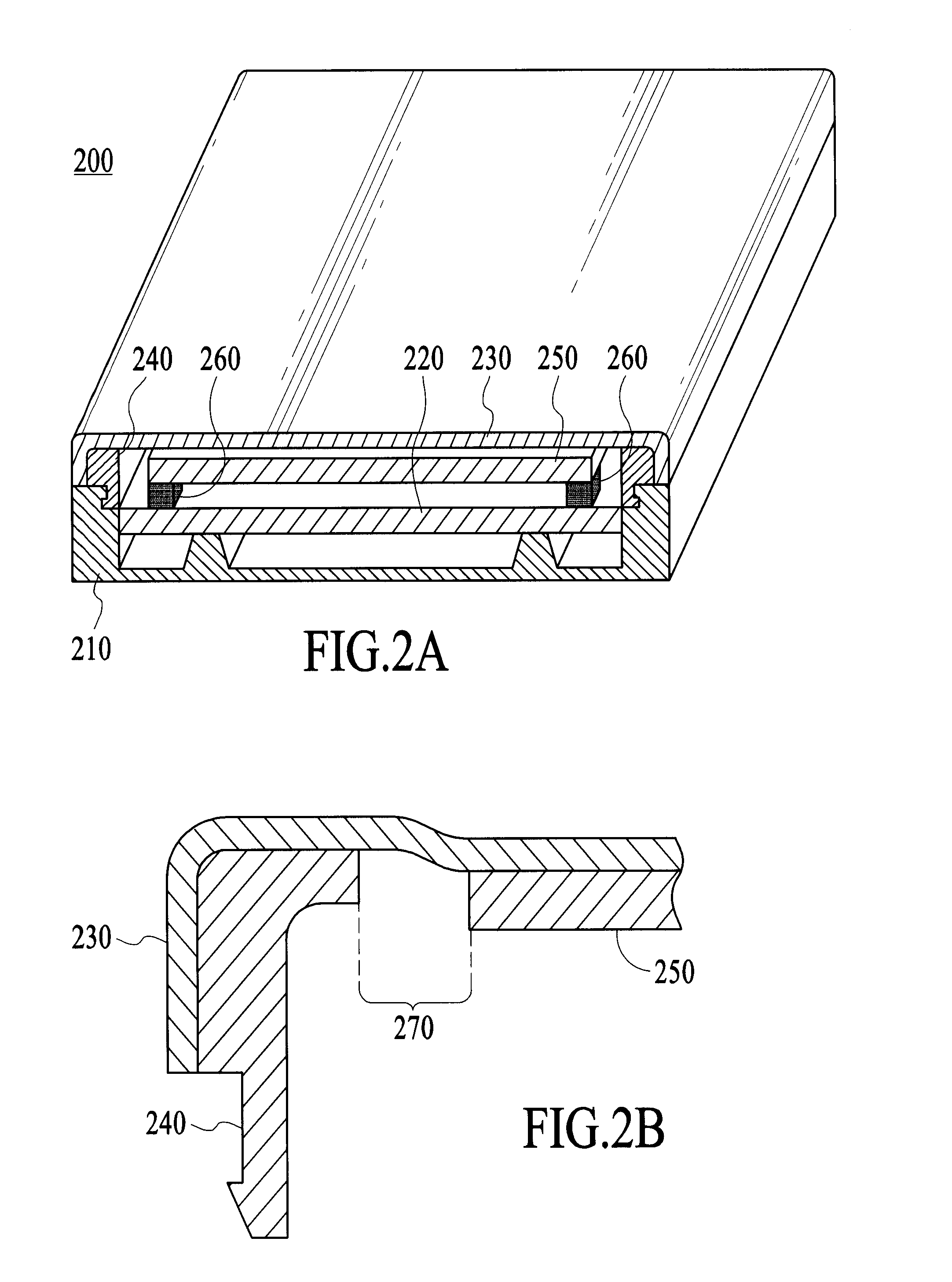
[0028]FIG. 2A is a cross-section of an electronic device 200 which utilizes a single-piece integrated front cover and display in accordance with one embodim...


PUM


Abstract

A single-piece top surface display and integrated front cover for an electronic device. In one embodiment, the cover comprises a thin, flexible, transparent layer coupled with a supporting structure. The flexible layer is supported above a display screen which is coupled with pressure activated sensors located under the display screen. The cover is dust-free, waterproof, and has a flat outer surface that is free of any steps or indentations. Users input data by applying pressure on the cover which causes the display screen to deflect and activate the sensors. The pressure exerted on the sensors is triangulated to register the position of the user input. In another embodiment, the cover is transparent, rigid, and directly contacts the pressure activated sensors which are located in front of the display screen or in the housing behind it. When pressure is applied to the cover, the cover deflects and activates the sensors. In both embodiments, an accelerometer identifies valid input events.

Description

BACKGROUND OF THE INVENTION[0001]1. Field of the Invention[0002]The present invention relates to the field of portable electronic devices that contain display devices. More particularly, the present invention relates to devices that contain a touch screen assembly that is activated by finger touch or by stylus pressure.[0003]2. Prior Art[0004]Advances in computer technology have enabled the further miniaturization of the components required to build computer systems. As such, new categories of computer systems have been created. One of the newer categories of computer systems is the portable, hand held, or “palmtop” computer system, also referred to as a personal digital assistant or PDA. Other examples of a portable computer system include electronic address books, electronic day planners, electronic schedulers and the like.[0005]A palmtop computer system is a computer that is small enough to be held in the user's hand and as such is “palm-sized.” As a result, palmtops are readily ...

Claims


Application Information

Patent Timeline
Patent Type & Authority Patents(United States)
IPC IPC(8): G09G5/00
CPCG06F1/1626G06F1/1637G06F1/1643G06F1/1684G06F1/1698G06F3/041G06F3/0414G06F3/045Y10S345/905G06F3/04142
Inventor GETTEMY, SHAWN R.HANSON, WILLIAM R.LAM, LAWRENCESLOTHOWER, ANNA P.
Owner QUALCOMM INC
Why Eureka
Try Eureka