Method of aligning optical-fibers, optical-fiber alignment device, and optical-fiber fusion splicer

a technology of optical fibers and splicers, applied in the field of methods, can solve the problems of difficulty in manually positioning the bare optical fiber to the v-groove, variations in operation speed according, and troublesome manual positioning of the bare optical fiber and the slit to each other

Inactive Publication Date: 2008-05-13
FUJIKURA LTD
View PDF5 Cites 8 Cited by
  • Summary
  • Abstract
  • Description
  • Claims
  • Application Information

AI Technical Summary

Benefits of technology

[0018]The eighth aspect of the invention provides an optical-fiber alignment device. The device includes: a first fiber positioner configured to align a first optical-fiber of a first optical-fiber cable; and a first cable positioner positioned near the first fiber positioner and being movable relative to the first fiber positioner to position the first optical fiber cable thereto, thereby allowing the first optical-fiber to be positioned relative to the first fiber positioner.
[0021]Thus, operators save positioning of the optical-fibers during aligning, contacting and fusion splicing of the optical-fibers, achieving easy and automatic alignment.

Problems solved by technology

In the former fusion splicer of the optical-fiber ribbon cord, the extremely narrow gap and width of the V-groove makes it very difficult for an operator to manually position the bare optical-fiber to the V-groove while visually checking this state.
This causes variations in operational speed according to differences in skill of operators.
In the latter optical-fiber fusion splicer, when the respective bare optical-fibers are to be inserted into the slits, it is troublesome to manually position the bare optical-fiber and the slit to each other.
When the bare optical-fibers are to be inserted or pulled out, the fixed slits necessarily move parallel to the bare optical-fibers, and the operator needs pay attention, thus rendering the operation difficult.

Method used


Image

  • Method of aligning optical-fibers, optical-fiber alignment device, and optical-fiber fusion splicer
  • Method of aligning optical-fibers, optical-fiber alignment device, and optical-fiber fusion splicer
  • Method of aligning optical-fibers, optical-fiber alignment device, and optical-fiber fusion splicer

Examples


Embodiment Construction

[0039]Exemplary embodiments of the invention will now be described below with reference to the accompanying drawings. The described exemplary embodiments are intended to assist the understanding of the invention, and are not intended to limit the scope of the invention in any way.

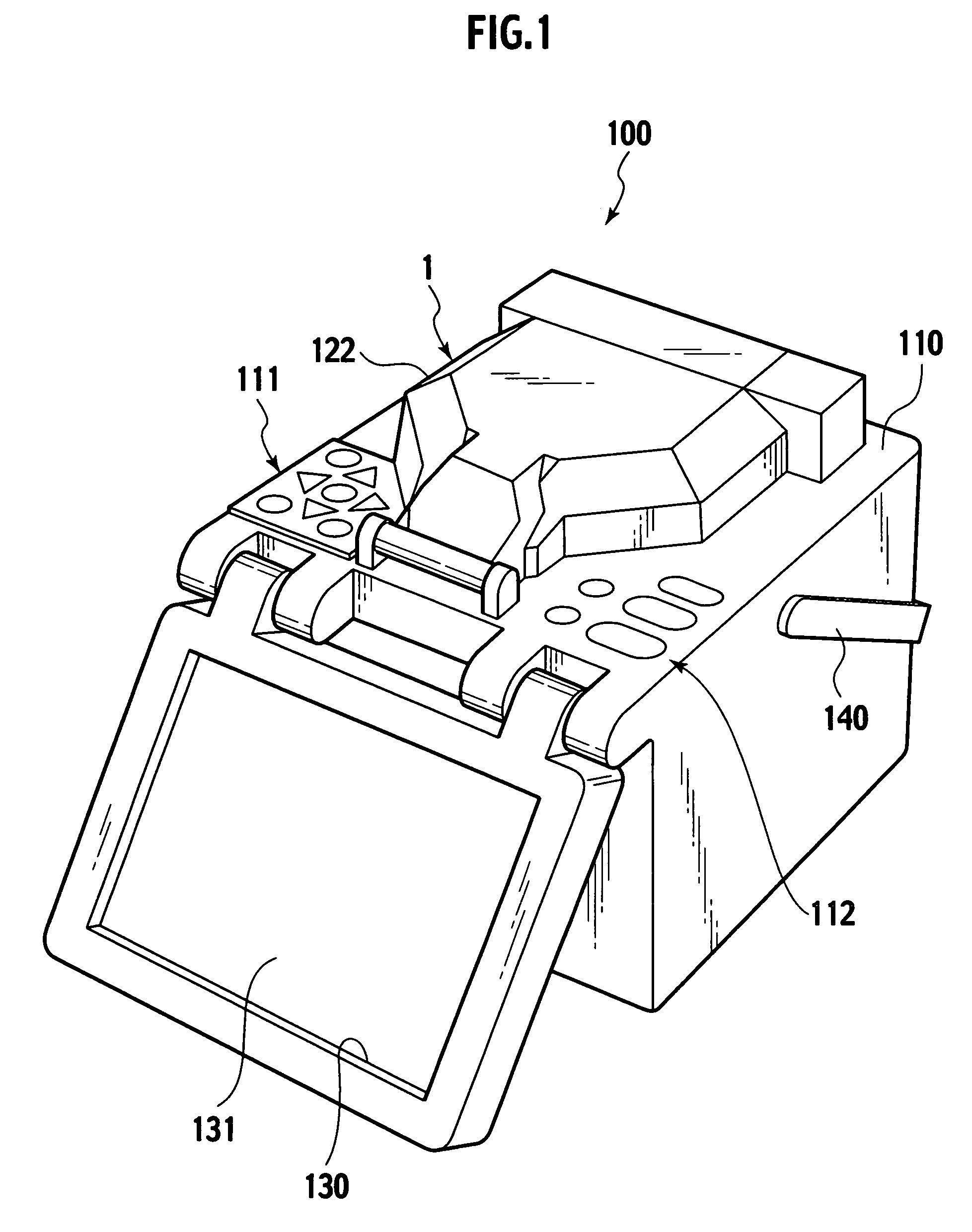
[0040]With reference to FIG. 1, an optical-fiber fusion splicer 100 includes a casing 110 provided at the top surface with a fusion splicing device 1. The fusion splicing device 1 is covered with a cover 122. The optical-fiber fusion splicer 100 includes a monitor 130 rotatably supported by the casing 110. The monitor 130 includes a display 131 which displays the process of fusion splicing optical-fibers. The top surface of the casing 110 of the fusion splicer 100 is provided with groups of switches 111 and 112 for operation. The fusion splicer 100 includes a handle 140 mounted on the casing 110. The handle 140 is used to carry the fusion splicer 100.

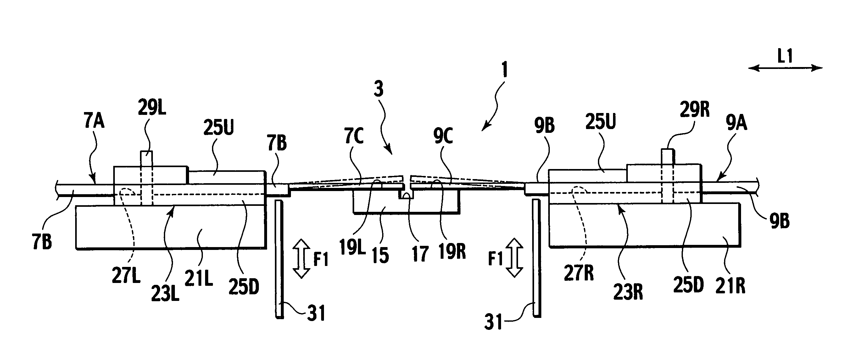
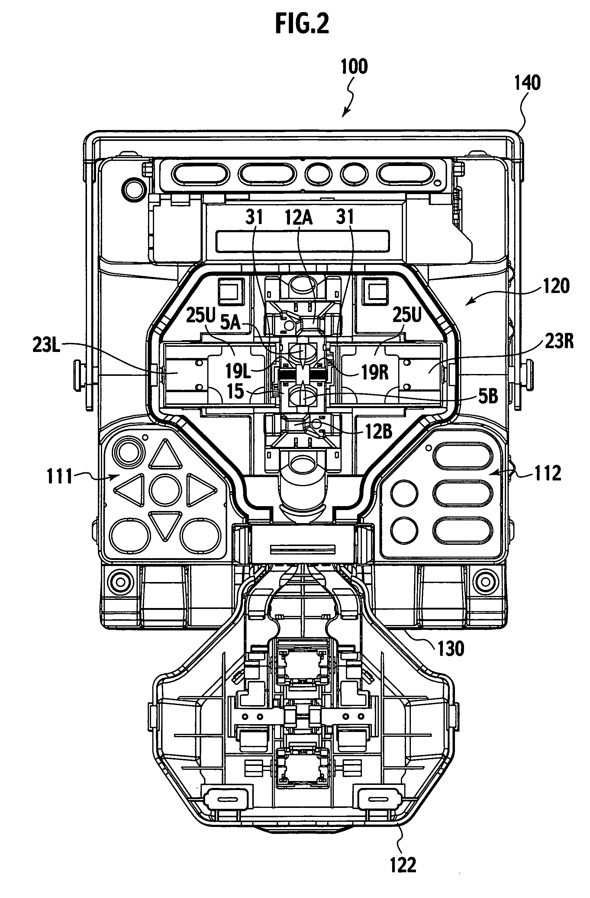
[0041]With reference to FIGS. 2 to 4, the fusion splicing...


PUM


Abstract

A method of aligning optical-fibers, including: holding a sheath of an optical-fiber ribbon cord using an optical-fiber holder so that distal ends of optical fibers extending from the sheath are located above grooves of a groove stage; arranging an optical-fiber guide on one side of the sheath, as the sheath is held by the optical-fiber holder, on a first side of the optical-fiber holder, wherein the optical-fiber guide has oblique portions adjacent to transverse sides of the sheath; moving the optical-fiber guide in a first direction toward the sheath so that at least one of the oblique portions aligns the sheath to the transverse center of the optical fiber guides; and moving the optical-fiber guide in a direction opposite the first direction to align the optical-fibers into the grooves of the groove stage.

Description

CROSS-REFERENCE TO RELATED APPLICATIONS[0001]This application is based upon and claims the benefit of priority from Japanese Patent Application. No. 2004-172730 filed on Jun. 10, 2004 in the Japanese Patent Office; the entire contents of which are incorporated herein by reference.BACKGROUND OF THE INVENTION[0002]The invention relates to a method of aligning optical-fibers. According to this method, an optical-fiber holder hold a sheath of an optical-fiber, the ends of bare optical-fibers exposed from the sheath are received and aligned in a groove of a groove stage provided inner side than the optical-fiber holder and aligned. This invention also relates to an optical-fiber alignment device and an optical-fiber fusion splicer using the method of aligning optical-fibers.[0003]A related optical-fiber fusion splicer includes an optical-fiber alignment device and fusion splicer means. The sheaths of ends of four-wire optical-fiber ribbon cords as a pair of optical-fibers are removed to ...

Claims


Application Information

Patent Timeline
Patent Type & Authority Patents(United States)
IPC IPC(8): G02B6/255G02B6/38
CPCG02B6/2551G02B6/2555
Inventor KANDA, YOSHIHARUTAKAHASHI, KENJI
Owner FUJIKURA LTD
Why Eureka
Try Eureka