Fixing Structure for a Vertical Tap

a fixing structure and tap technology, applied in the field of fixing structure, can solve problems such as inconvenient assembly

Inactive Publication Date: 2009-07-09
HORNG LAI IND CO LTD
View PDF4 Cites 10 Cited by
  • Summary
  • Abstract
  • Description
  • Claims
  • Application Information

AI Technical Summary

Benefits of technology

[0008]Another object of the present invention is to provide a fixing structure for a vertical tap, the lower end of the vertical tap of which is straightly secured to the ground by way of the mounting member and the fitting member so that the vertical tap may automatically aligned with the bathtub, and then the screwed holes of the fixing ring may be utilized to screw the bolt and the vertical tap together, thereby engageably securing the vertical tap.
[0009]In accordance with one aspect of the present invention, there is provided a fixing structure for a vertical tap comprising a vertical tap, a mounting member, a fitting member, a fixing ring, and a decorative loop, wherein the mounting member for being secured into the ground includes a receiving chamber arranged on the top thereof and having two retaining tabs attached on the upper end thereof, the upper end of the fitting member screws with the lower end of the vertical tap, and the fitting member includes two opposite fastening projections disposed on the outer periphery at the lower end thereof and extending outwardly therefrom, the fixing ring is fitted onto the external rim of the vertical tap and then secured in a wooden floor by using a number of wood screws and further engaged with the internal rim of the vertical tap by way of a bolt, the decorative loop is covered onto the fixing ring, thereby supporting and securing the vertical tap easily.

Problems solved by technology

Furthermore, in order to align an outlet pipe of the vertical tap 10 with the bathtub, the vertical tap 10 has to be further fixed by virtue of the wood screws 30 after being positioned, causing an inconvenient assembly.

Method used


Image

  • Fixing Structure for a Vertical Tap
  • Fixing Structure for a Vertical Tap
  • Fixing Structure for a Vertical Tap

Examples


Embodiment Construction

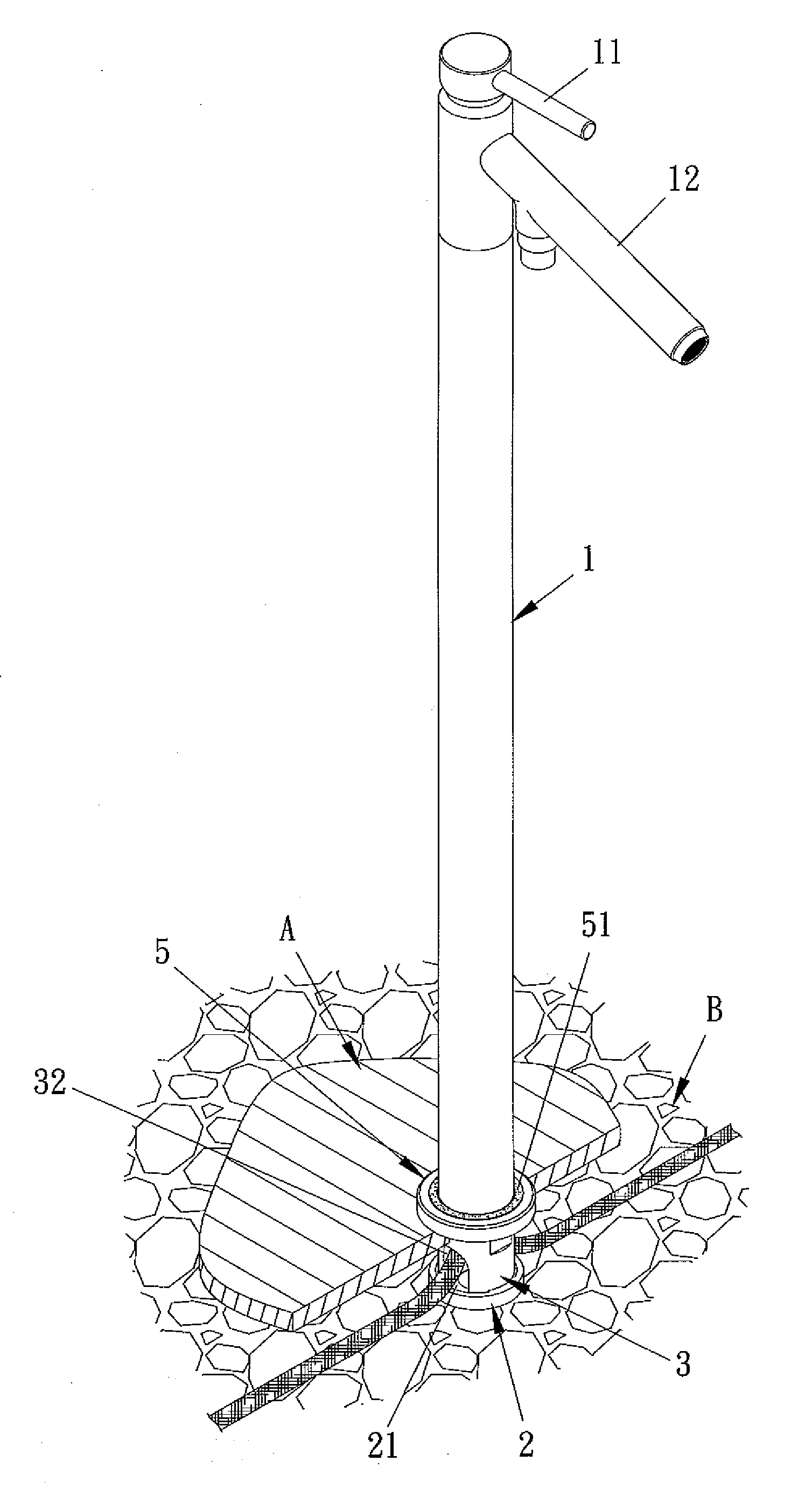
[0016]Referring to FIGS. 3-5, a fixing structure for a vertical tap in accordance with the present invention comprises a vertical tap 1, a mounting member 2, a fitting member 3, a fixing ring 4, and a decorative loop 5, wherein the vertical tap 1 includes a control lever 11 and an outlet pipe 12, both of which are disposed thereon, and includes internal threads 13 formed on the inner sidewall at the lower end thereof. The mounting member 2 is constructed in the form of a disc and includes a circular receiving chamber 21 arranged on the top thereof, at the bottom of which are provided with three locking holes 211. On the upper end of the receiving chamber 21 are attached two retaining tabs 212 relative to each other. The fitting member 3 includes a size variable segment 31 with external threads 311 affixed on the upper end thereof and includes two opposite gaps 32 for inserting cool and hot water supply tubes therein respectively secured on the lower end thereof, and includes two opp...


PUM


Abstract

A fixing structure for a vertical tap comprises a vertical tap, a mounting member, a fitting member, a fixing ring, and a decorative loop, wherein the mounting member for being secured in the ground includes a receiving chamber arranged on the top thereof and having two retaining tabs attached on the upper end thereof, the upper end of the fitting member screws with the lower end of the vertical tap, and the fitting member includes two opposite fastening projections disposed on the outer periphery at the lower end thereof and extending outwardly therefrom, the fixing ring is fitted onto the external rim of the vertical tap and then secured in a wooden floor by using a number of wood screws and further engaged with the internal rim of the vertical tap by way of a bolt, the decorative loop is covered onto the fixing ring, thereby supporting and securing the vertical tap easily.

Description

BACKGROUND OF THE INVENTION[0001]1. Field of the Invention[0002]The present invention relates to a fixing structure, and more particularly to a fixing structure for a vertical tap that may effectively and easily securing the vertical tap.[0003]2. Description of the Prior Arts[0004]As shown in FIGS. 1 and 2, a conventional fixing structure for a vertical tap includes a vertical tap 10, the bottom of which is directly affixed to a wooden floor A by using a screwing seat 20. In assembly, external threads 201 of the screwing seat 20 is screwed with internal threads 101 of the bottom of the vertical tap 10, and a plurality of wood screws 30 are provided to insert through a number of predetermined through holes 202 of the screwing seat 20, such that the vertical tap 10 may be locked in the wooden floor A.[0005]Nevertheless, such a conventional fixing structure may have a disengagement of the vertical tap 10 from the wooden floor A, because the vertical tap 10 is simply screwed with the sc...

Claims


Application Information

Patent Timeline
Patent Type & Authority Applications(United States)
IPC IPC(8): E03C1/04
CPCE03C1/0401E03B9/20Y10T137/698Y10T137/9464
Inventor SHIEH, MING-DANG
Owner HORNG LAI IND CO LTD
Why Eureka
Try Eureka