
Coupling Device

a technology of coupling device and liquid, which is applied in the field of handling, can solve the problems of high cost, high cost, and high cost of providing a container with a permanent cap that comprises such an expensive part, and achieves the effect of improving the coupling

Inactive Publication Date: 2016-06-30
BASF AG
View PDF9 Cites 7 Cited by
  • Summary
  • Abstract
  • Description
  • Claims
  • Application Information

AI Technical Summary

Benefits of technology

The present invention is a coupling device for containers, which allows for draining and venting the container simultaneously. The device has a dual function closure, which facilitates draining, venting, and washing of the container. The device also facilitates automatic resealing of the container when the coupling device is removed. The device is easy to engage and has a tactile positioning mechanism. It includes a protrusion and recess to ensure proper alignment, and a vertical orientation to prevent misuse and make the equipment safer. The technical effects of this invention include improved usability, efficiency, safety, and reliability.

Problems solved by technology

In many technical fields, like for example in the field of liquids, liquids are used which may be hazardous for the user or operator.
However, the currently known systems are only available for large multi-trip containers or cause high costs due to the employment of complicated valve technology within the dispensing device of such closed transfer system.
Due to the high costs of such spring based opening- and closing-mechanisms, these opening and closure mechanisms are normally provided within the centrally used dispensing device, which is used for a plurality of different containers.
Providing a container with a permanent cap that comprises such an expensive, metal spring based opening- and closing-mechanism is economically not desirable as the containers are used only once.
Moreover, the container is not easily recycled if it comprises a metal spring.
Hence, after decoupling the dispensing device the seal foil is attached to the container opening in a destroyed configuration and no automatic closure of the opening of the container is provided after decoupling the dispensing device.
However, such a situation disadvantageously bares the risk of both contamination and leakage.
Further, an unintentional decoupling during the process of draining may cause large spillages and may create an additional operator risk.
However, the inventors of the present invention found that it may be the case that the movement of the sleeves can be incomplete due to an increase in friction or failure of the spring to overcome the friction leaving the probes open while the coupling device is removed from the cap and the container.
This may allow liquid to escape which in turn increases potential contamination of the operator.

Method used


Image

  • Coupling Device
  • Coupling Device
  • Coupling Device

Examples


Embodiment Construction

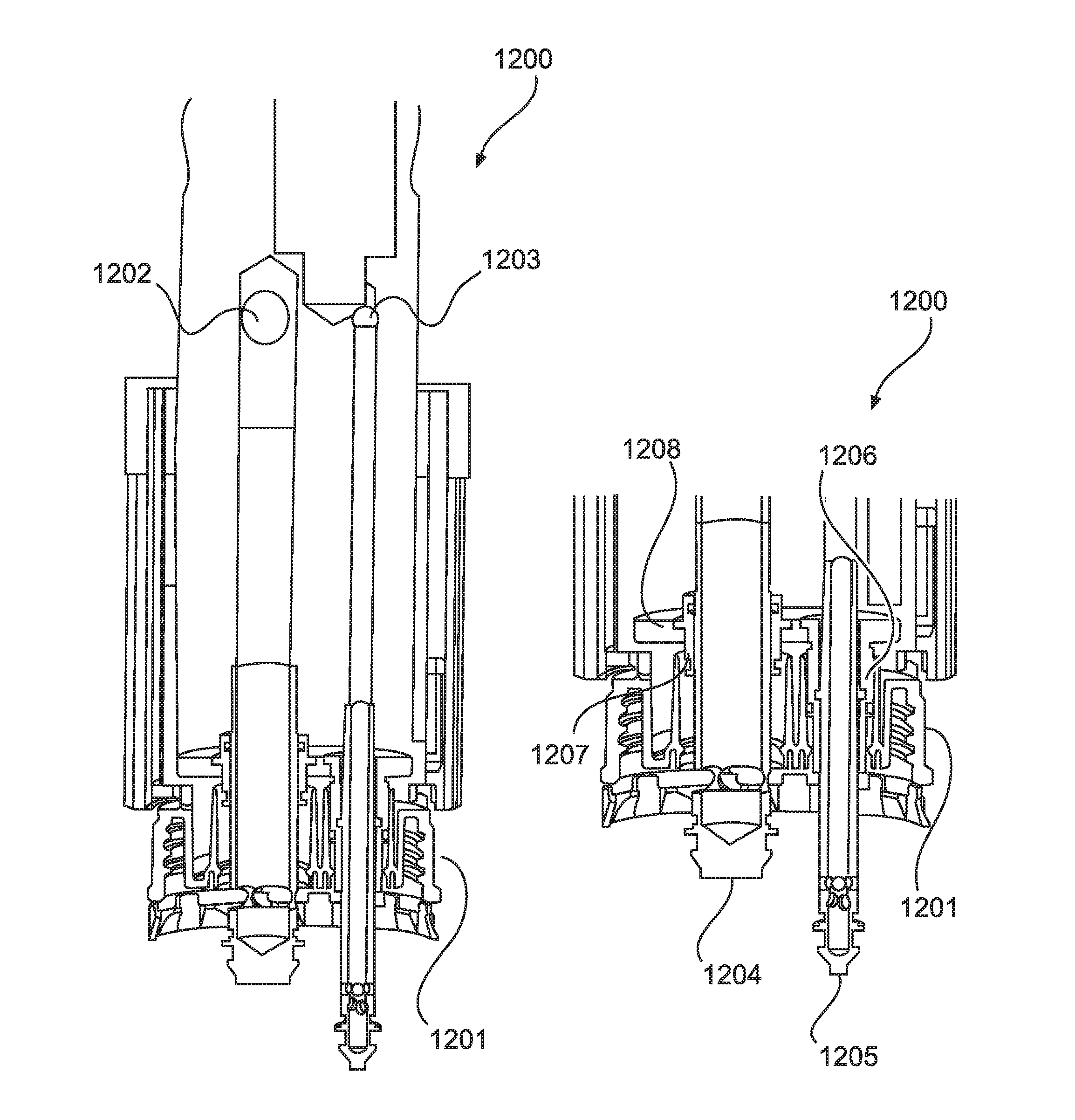
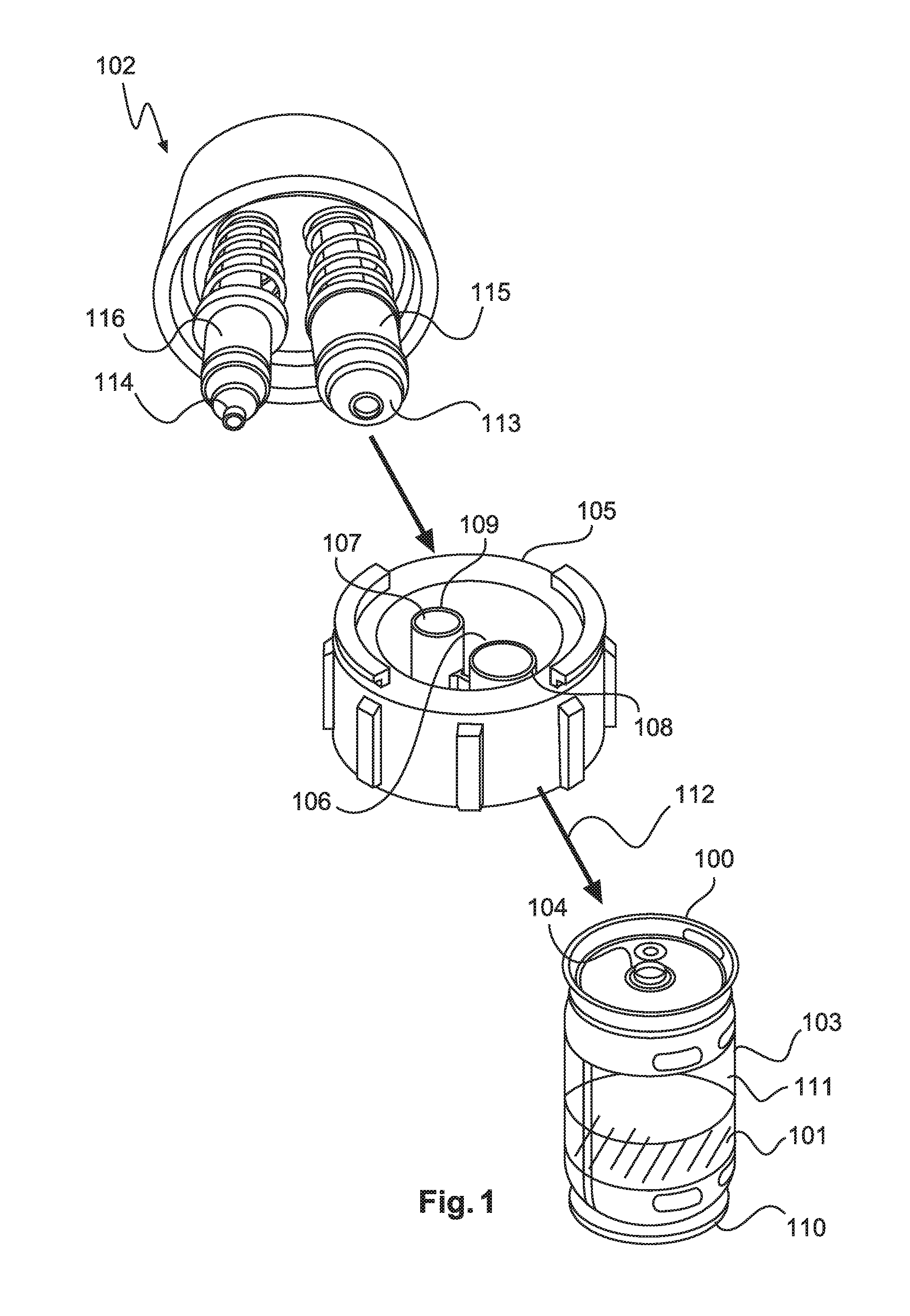
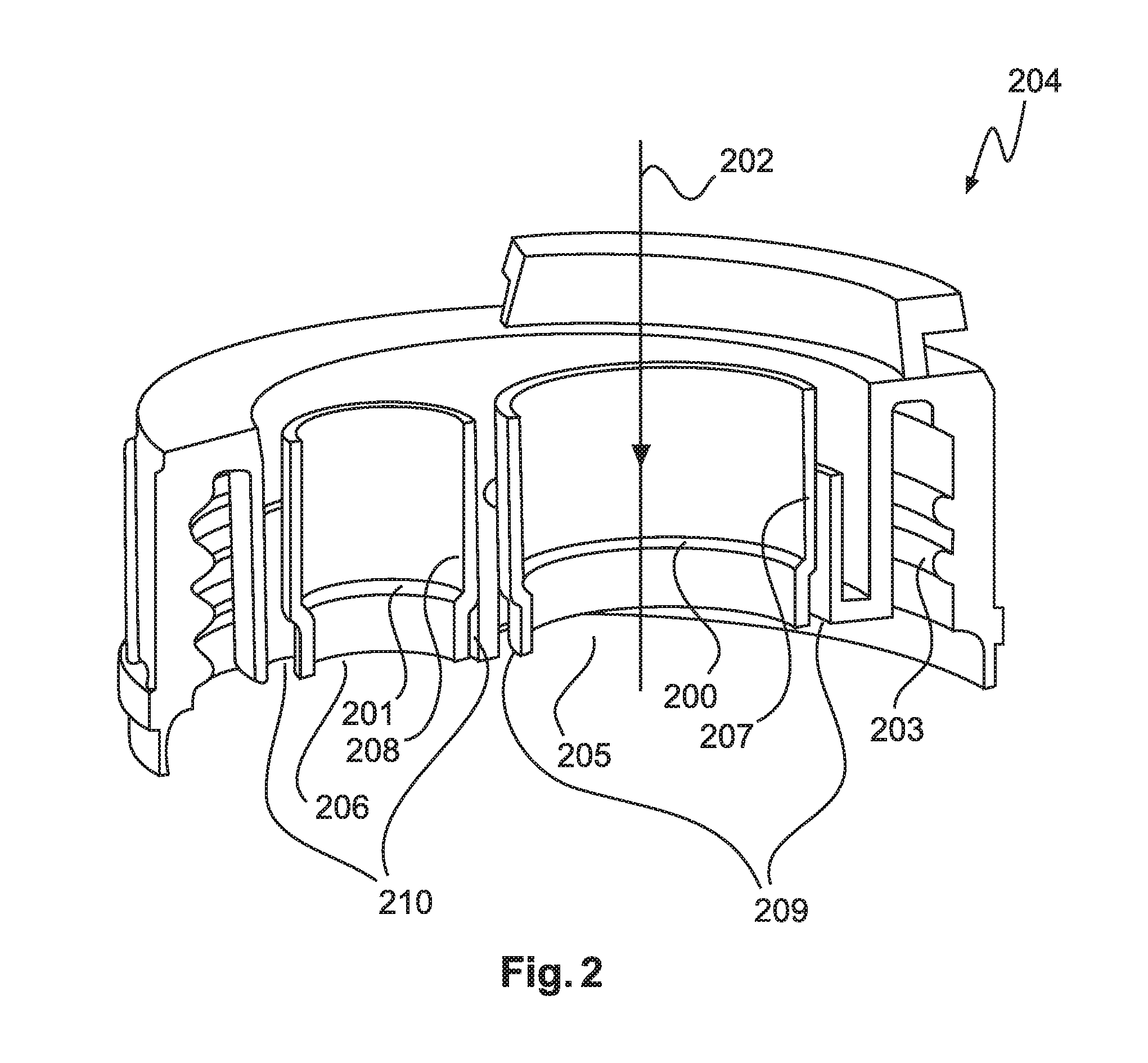
[0119]The embodiment of the coupling device of FIG. 1 also comprises a first probe 113 and a second probe 114 wherein the first probe comprises a first sleeve 115 and the second probe comprises a second sleeve 116. FIG. 1 further shows a container 100 for transporting and storing a liquid and with a dual functional closure. The container 100 of FIG. 1 comprises a container body 103 with at least one inlet opening 104. A springless cap 105 is shown which is configured to close the inlet opening of the container body. The cap 105 is embodied as a relatively low cost and disposable product. As illustrated by arrow 112 the cap can be attached to the inlet opening of the container body by appropriate attachment means. The cap 105 comprises a first opening 106 and a second opening 107 both extending vertically, i.e. in the direction from the top to the bottom of FIG. 1. This direction is termed axially and is precisely defined, in general, with respect to axis 202 of FIG. 2. In the first ...


PUM


Abstract

The present invention relates to a coupling device configured to be mechanically coupled to a springless cap of a container to be in a coupled configuration. The coupling device comprises a first probe configured to be inserted into a first opening of the cap, a second probe configured to be inserted into a second opening of the cap, a first sleeve configured to cover a first extraction aperture of the first probe and a second sleeve configured to cover a second extraction aperture of the second probe. The first sleeve is slideably attached to the first probe and the second sleeve is slideably attached to the second probe. Furthermore, the coupling device is configured, when in the coupled configuration, to disengage a first closure insert of the cap from a first shoulder of the cap by axially pushing the first closure insert with the first probe. The coupling device is also configured, when in the coupled configuration, to disengage a second closure insert of the cap from a second shoulder of the cap by axially pushing the second closure insert with the second probe. In an embodiment the coupling device comprises a probe translation control mechanism and / or a sleeve translation control mechanism. The plugs in the cap may have a spring function derived from a material memory in the legs of the plug and this is used to retain the plugs in position and sealed.

Description

FIELD OF THE INVENTION[0001]The present invention relates to the handling of liquids and solid state media stored in containers which are opened and closed by means of a coupling device. In particular, the present invention relates to a coupling device configured to be coupled to a cap of a container, a system for draining and venting a container and a method of mechanically coupling a coupling device to a cap of a container.BACKGROUND OF THE INVENTION[0002]In many technical fields, like for example in the field of liquids, liquids are used which may be hazardous for the user or operator. It is therefore a desire to provide for risk mitigation measures that reduce the chances of exposing the user with the chemically active substances. Moreover, during the transfer of the liquid the avoidance of spillages is desirable as well. Further, in some industries contamination of the liquids is strictly forbidden, like for example in food and beverage industries. Therefore, closed transfer sy...

Claims


Application Information

Patent Timeline
IPC IPC(8): B67D7/02
CPCB67D7/0288B67D1/0802B65D43/0277B65D45/02B65D47/14
Inventor HUBER, ROBERTSASTURAIN, JUANGARNETT, RICHARD
Owner BASF AG
Learn More