Electric compressor and assembling method thereof

a compressor and electric technology, applied in the field of compressors, can solve the problems of increasing compressor costs, and achieve the effects of improving compressor quality, excellent assembling operability, and stabilizing compressor quality

Inactive Publication Date: 2005-06-16
PANASONIC CORP
View PDF4 Cites 7 Cited by
  • Summary
  • Abstract
  • Description
  • Claims
  • Application Information

AI Technical Summary

Benefits of technology

[0024] With this method, by fastening the unitized compression mechanism and the unitized electric motor in the axial direction, the centering operation of both the elements can be carried out, the assembling operability is excellent, variation of the assembling precision can be suppressed, and the quality of the compressor can be stabilized.

Problems solved by technology

According to such a centering method, however, a strict dimensional tolerance is required between the pin hole position and the axial center, high precision working is required for the inserting pins and the pin holes, and this becomes a factor which increases costs of the compressor.

Method used


Image

  • Electric compressor and assembling method thereof
  • Electric compressor and assembling method thereof
  • Electric compressor and assembling method thereof

Examples


first embodiment

[0031] (First Embodiment)

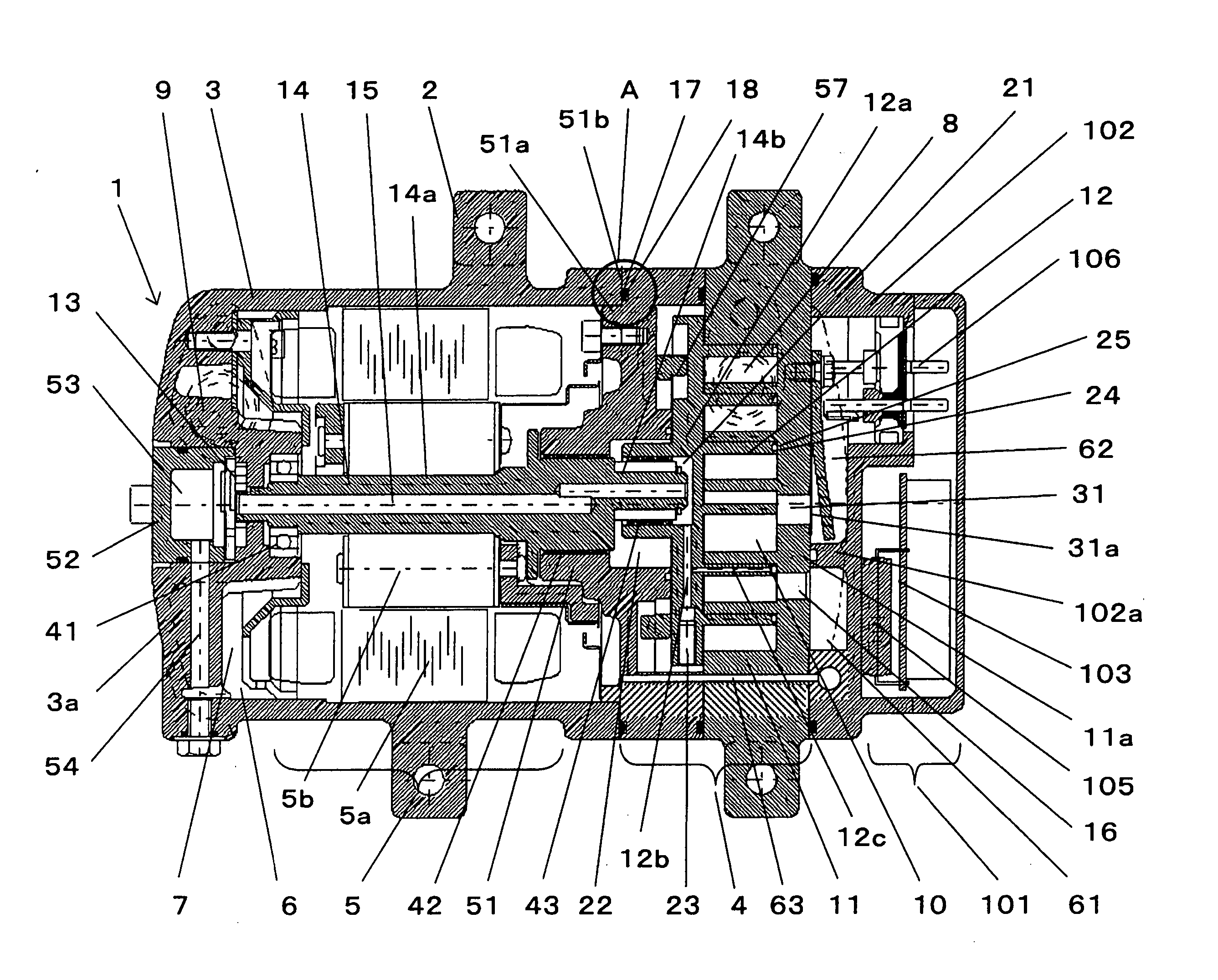
[0032]FIG. 1 shows one example of a lateral type electric compressor which is disposed laterally by two pairs of legs 2 provided around a body of an electric compressor 1.

[0033] In FIG. 1, the electric compressor 1 comprises a bottomed cylindrical container 3 in which an electric motor 5 is accommodated. The electric motor 5 comprises a stator 5a and a rotor 5b. The electric compressor 1 further comprises a compression mechanism 4 which is fastened to the container 3 in its axial direction by using a bolt (not shown) and which is driven by a drive shaft 14 of the electric motor 5.

[0034] A liquid reservoir 6 for storing liquid used for lubricating various sliding parts including the compression mechanism 4 is provided in the container 3. The container 3 is provided at its axial one end with a motor driving circuit 101 which drives the electric motor 5.

[0035] A gas refrigerant is used as a refrigerant in the electric compressor 1. Liquid such as lubricant 7...

second embodiment

[0060] (Second Embodiment)

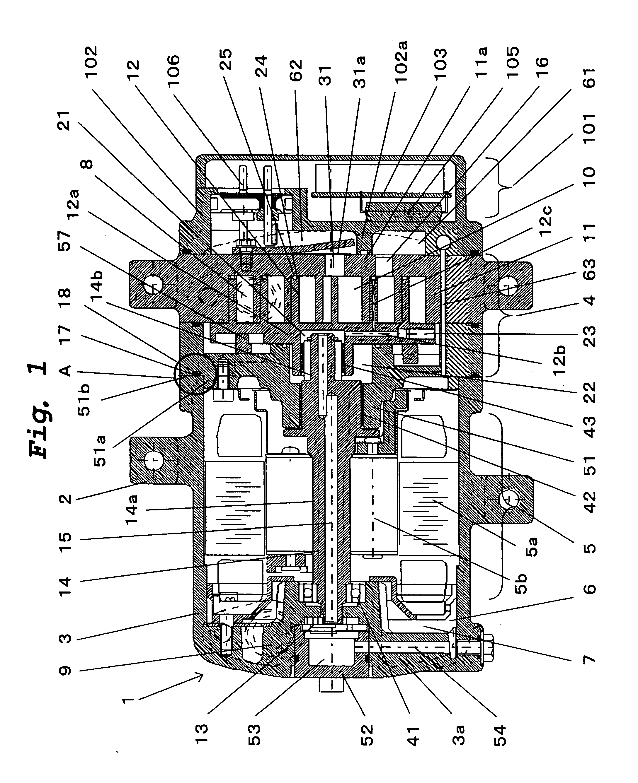
[0061] In FIG. 2, in the electric compressor 1 shown in the first embodiment, the seal groove 17 is formed in the outer periphery of the flange 51a, and the annular seal ring 18 is disposed in the seal groove 17.

[0062] With this structure also, reliable sealing effect can be obtained.

third embodiment

[0063] (Third Embodiment)

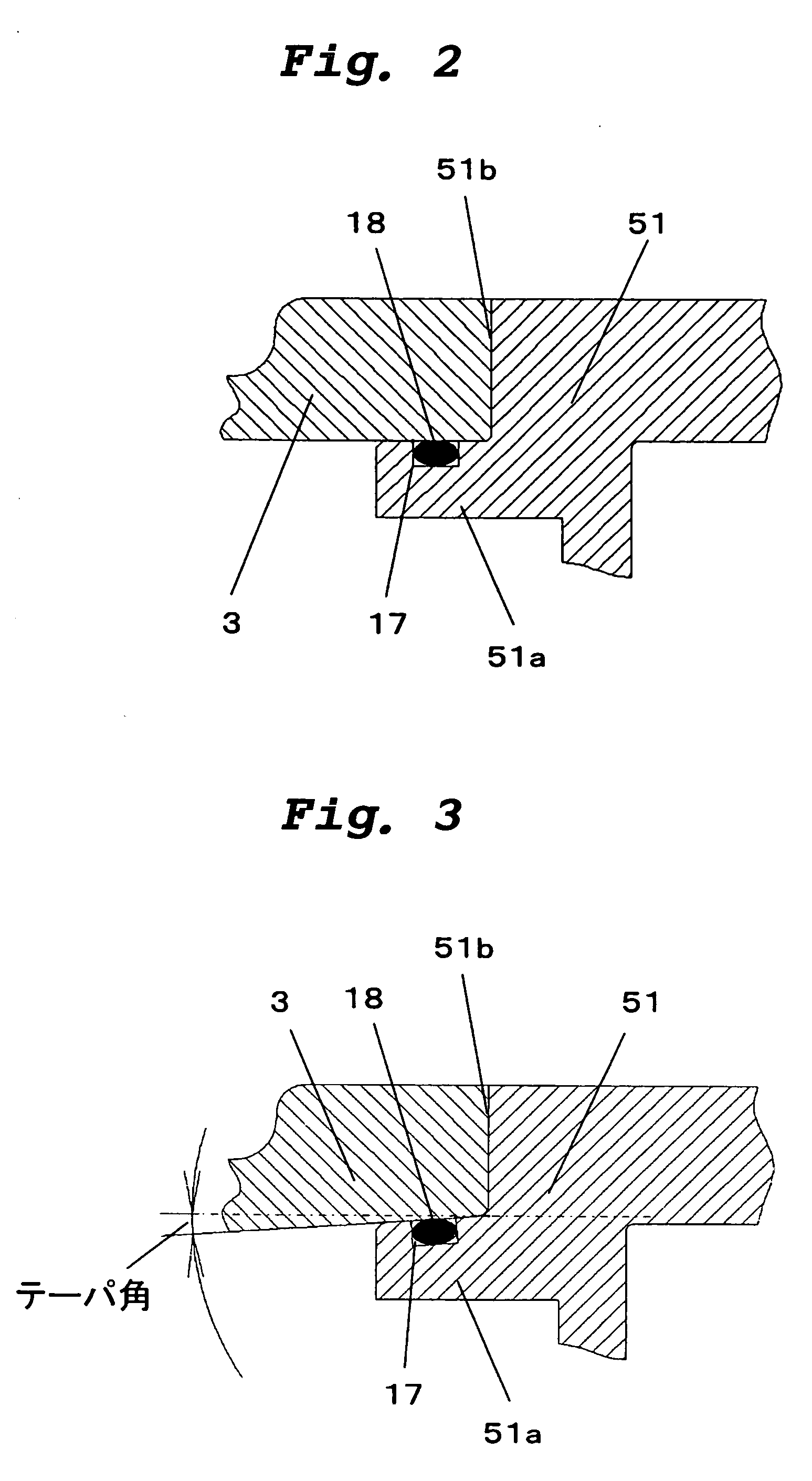
[0064] In FIG. 3, in the second embodiment, an outer periphery of the flange 51a is formed into a truncated shape such that the outer periphery becomes gradually thinner toward the opening end, and the inner peripheral surface of the container 3 is formed such that the thickness thereof is gradually reduced toward the opening end.

[0065] The flange 51a is formed at its outer periphery with the seal groove 17, and the annular seal ring 18 is disposed in the seal groove 17.

[0066] With this structure, cylindrical tapered surfaces of the outer peripheral surface of the flange 51a and the inner peripheral surface of the container 3 abut against each other. With this, the fitting operation can smoothly be carried out, and they can be assembled without damaging the seal ring 18.


PUM


Abstract

The present invention provides an electric compressor in which the centering operation between a container and a main bearing member can be carried out precisely, and the compressor can easily be assembled. A main bearing member is provided at its peripheral edge with an inserting portion and an abutting portion, an outer diameter of the inserting portion is set smaller than that of the abutting portion. The outer diameter of the inserting portion is set slightly smaller than an inner diameter of an opening end of the container. With this structure, a centering operation can be carried out precisely and easily, and the reliability and performance of the compressor are enhanced, and costs thereof can be reduced.

Description

TECHNICAL FIELD [0001] The present invention relates to a compression mechanism, an electric motor which drives the compression mechanism through a drive shaft, an electric compressor such as a scroll compressor having a container in which the electric motor is accommodated, and an assembling method of the electric compressor. BACKGROUND TECHNIQUE [0002] Generally, a pressure-proof container is used in this kind of compressor, and a scroll compressor or a rotary compressor is employed as the compression mechanism, and a stator and a rotor made of iron-based material around which copper wires are wound are used as the electric motor. [0003] As an electric compressor used in a living space, a hermetical electric compressor comprising an iron housing is widely known. As an electric compressor used for air conditioning in a vehicle, a semi-hermetical electric compressor comprising a light aluminum housing has become mainstream because such an electric compressor can easily be mounted on...

Claims


Application Information

Patent Timeline
Patent Type & Authority Applications(United States)
IPC IPC(8): F01C21/10F04C18/02F04C23/00F04C27/00
CPCF01C21/10F04C18/0215F04C2230/603F04C27/00F04C23/008
Inventor MAKINO, MASAHIKOOGAWA, NOBUAKIFUJIWARA, YUKIHIRO
Owner PANASONIC CORP
Why Eureka
Try Eureka