Disk-rotating motor and disk-driving device

a technology of a rotating motor and a drive shaft, which is applied in the direction of sliding contact bearings, rigid support of bearing units, instruments, etc., can solve the problems of insufficient holding strength, inability to expect sufficient strength, and reliability may be degraded, so as to reduce the number of parts, and improve the effect of assembly operability

Active Publication Date: 2013-02-28
MINEBEAMITSUMI INC
View PDF11 Cites 2 Cited by
  • Summary
  • Abstract
  • Description
  • Claims
  • Application Information

AI Technical Summary

Benefits of technology

[0018]According to the above configuration, since the bracket has a function of supporting load of the rotor section in a thrust direction, the holding force thereof is not influenced by the member tightening. Also, since the bracket can be integrally formed by press processing, the member is relatively inexpensive, the number of parts can be reduced and the assembling operability is also improved.
[0019]Also, the inner diameter of the shaft-bearing, which is a rotational center of a motor, is directly press-fitted. Thus, a distance variation from a motor fixing position to the rotational center can be secured just by the precision of the single item of the bracket, so that the super-high precision can be secured. Also, the shaft-bearing housing and the bracket can be tightened based on the high reliability by the combination use of the press fitting and the adhesion, so that it can be easily configured in a motor which requires the thinning and the size-reduction. Since it is possible to secure a large area for tightening the shaft-bearing housing, the motor can be useful in a device for vehicle mount with the excessive vibration.

Problems solved by technology

Hence, as the motor is made to be smaller, there occurs a problem where the holding strength becomes insufficient in the support of the load of the rotor section 101 in the thrust direction.
Hence, it is not possible to expect the sufficient strength.
Also, the adhesive flows to a shaft-bearing, so that the reliability may be degraded.
Also, the fixing by the welding is difficult to implement due to its structural reason.
In view of the assembling precision, particularly a distance variation from a motor fixing position to a rotational center upon the assembling, according to the method of press fitting an outer diameter part of the shaft-bearing, since the outer diameter part of the shaft-bearing is worn upon the press fitting and the coaxial precision between the outer diameter part and the inner diameter part is accumulated, there is a limit in securing the high precision.
Also in the shaft-bearing holding structure shown in FIG. 6, the fixing by the welding is difficult to implement due to its structural reason, like the configuration shown in FIG. 5.
Also, the fixing by the adhesion is not useful because the adhesive may flow to a lower surface of the bracket.
Also, like the configuration shown in FIG. 5, the distance variation from the motor fixing position to the rotational center has a limit in securing the high precision because a variation such as plate thickness of the shaft-bearing housing is accumulated.
In any case, it is clear that as the motor becomes smaller and thinner, it is difficult to secure the tightening strength only by the press fitting fixing.
Thus, it cannot be said that the reliability is very high in a device for vehicle mount in which the vibration is excessively generated.
However, there is a limit in securing the high precision in view of the wear of the jig or maintenance precision while considering the mass production.

Method used


Image

  • Disk-rotating motor and disk-driving device
  • Disk-rotating motor and disk-driving device
  • Disk-rotating motor and disk-driving device

Examples


embodiments

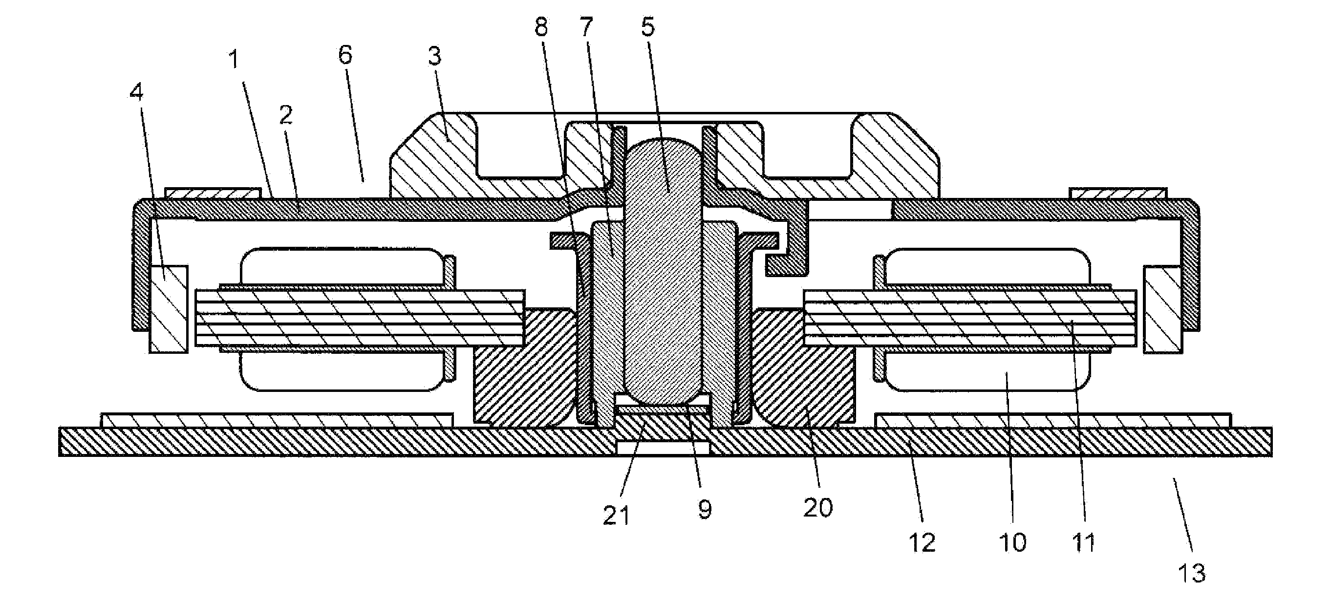
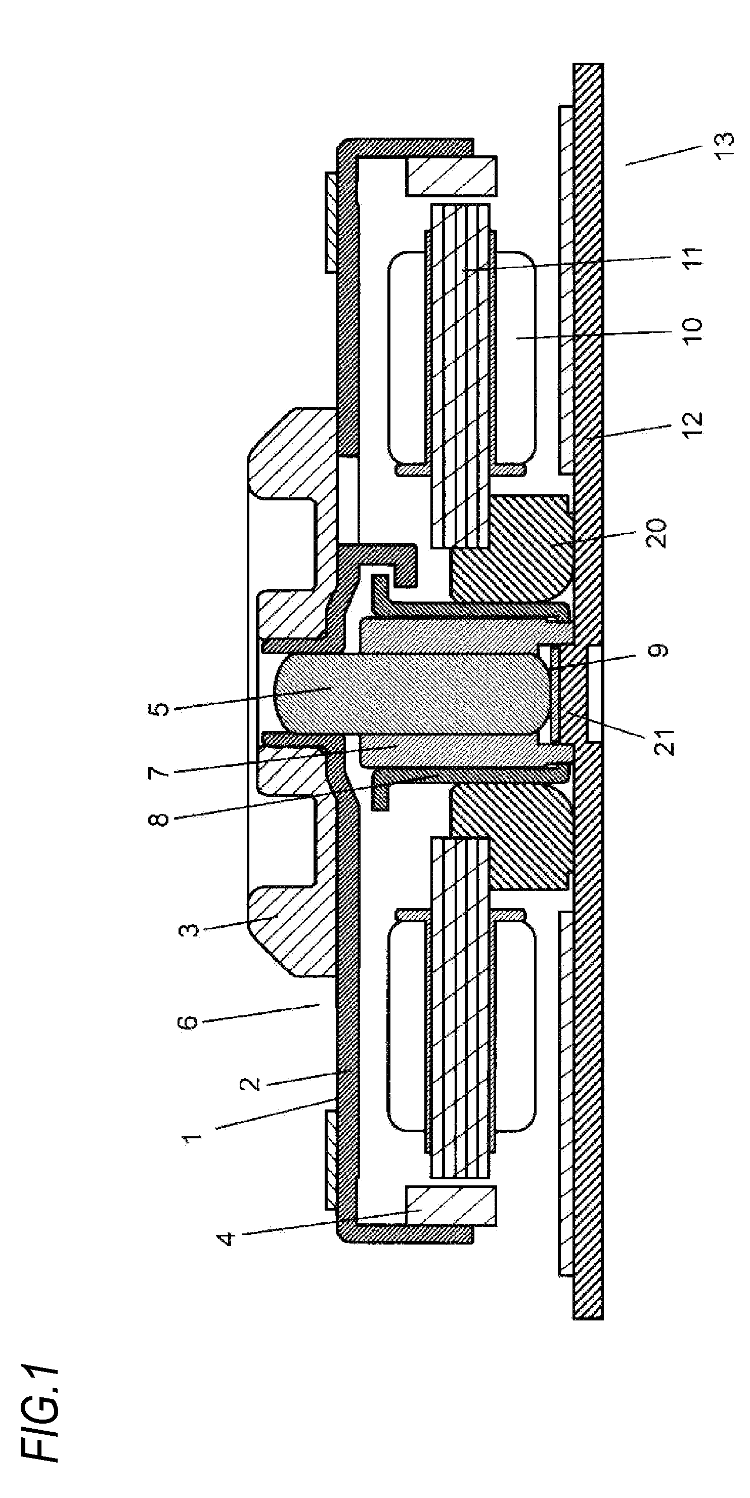
[0031]FIG. 1 is a sectional view showing a structure of a disk-rotating motor according to an embodiment of the present invention. In FIG. 1, the disk-rotating motor includes a rotor section 6 and a stator section 13.

[0032]The rotor section 6 includes a turntable part 1, a rotor frame 2, a disk-aligning member 3, a rotor magnet 4 and a shaft 5.

[0033]The rotor frame 2 has a substantial cup shape made of metal, and the shaft 5 is fixed to a center of the rotor frame 2. The rotor magnet 4 having a ring shape is fixed on a cylindrical inner periphery of the rotor frame 2. Also, a disk such as optical disk, like CD and DVD is mounted on the turntable part 1 which is a circular plane part of an upper surface of the rotor frame 2. Also, the rotor section 6 includes the disk-aligning member 3 having a substantially circular shape so as to align an inner diameter part of the disk. The disk-aligning member 3 supports the disk together with the turntable part 1.

[0034]In the meantime, the stato...


PUM

PropertyMeasurementUnit
inner diameteraaaaaaaaaa
outer diameteraaaaaaaaaa
shock resistanceaaaaaaaaaa

Abstract

A disk-rotating motor includes a rotor section including a rotor magnet attached to a rotor frame and a shaft fixed to a center of the rotor frame, and a stator section including a shaft-bearing which bears the shaft, wherein the stator section includes the shaft-bearing, a shaft-bearing housing which holds the shaft-bearing, a thrust plate which bears the shaft in an axis direction, a stator core which is arranged to face the rotor magnet and provided with wire-winding, a core holder which holds the stator core, and a bracket which holds the shaft-bearing housing. The bracket has a projecting part which fixes the shaft-bearing at a central part thereof, an inner diameter part of the shaft-bearing is press-fitted to be tightened to the projecting part, and an outer diameter part of the shaft-bearing housing is adhered to be tightened to an inner diameter part of the core holder.

Description

TECHNICAL FIELD[0001]The present invention relates to a disk-rotating motor and a disk-driving device for rotating and driving a disk such as optical disk like CD or DVD, and more particularly, to a shaft-bearing holding structure and a tightening of a shaft-bearing holding member.BACKGROUND ART[0002]Conventionally, for a shaft-bearing holding structure configured in a disk-rotating motor which is used in a disk-driving device which requires a thinning and size-reduction, a variety of shaft-bearing holding structures such as a shaft-bearing holding structure which uses a sintered member of the same material as a shaft-bearing, a shaft-bearing holding structure which uses a cutting processing member made of brass, and the like have been suggested. Also, in order to cope with a recent trend of the rapid cost-down, it is required to configure the shaft-bearing holding structure by combining members as inexpensive as possible. At the same time, the needs for reliability are also increas...

Claims


Application Information

Patent Timeline
Patent Type & Authority Applications(United States)
IPC IPC(8): H02K7/08
CPCF16C17/10F16C33/1065F16C2370/12H02K7/08H02K5/1675F16C35/02G11B19/2009Y10T29/49009
Inventor NISHIKATA, TOSHIYUKIMASUDA, KUMIO
Owner MINEBEAMITSUMI INC
Why Eureka
Try Eureka