Optical laminated bodies, lighting equipment and area luminescence equipment

a technology of optical laminated bodies and lighting equipment, applied in the field can solve the problems of difficult to improve the brightness of area luminescence equipment and complicated manufacturing operations, and achieve the effects of reducing the number of parts, simplifying manufacturing and assembly operations, and preventing optical loss by interfacial reflection

Inactive Publication Date: 2005-12-06
3M INNOVATIVE PROPERTIES CO
View PDF4 Cites 80 Cited by
  • Summary
  • Abstract
  • Description
  • Claims
  • Application Information

AI Technical Summary

Benefits of technology

[0015]The optical laminated bodies of the present invention are characterized in that a polarizing layer comprises a reflective polarizing film, and both of a first transparent film disposed closely to a front surface of the polarizing layer and a second transparent film disposed closely to a back surface of the polarizing layer are diffusive films. Since the optical laminated bodies comprise diffusive films, an upper diffusive plate and / or a lower diffusive plate of the prior art are not required when the bodies are incorporated into the area luminescence equipment. Accordingly, the number of parts can be reduced, making it possible to simplify the manufacturing and assembly operations. The area luminescence equipment of the invention can also eliminate the optical surface between the diffusive plate and optical film. Accordingly, the optical loss by the interfacial reflection can be prevented, making it possible to facilitate an increase in brightness of the area luminescence equipment. By the effect of the diffusive film closely disposed to the polarizing layer, it is therefore possible to improve brightness without negatively or adversely influencing on the visual property.
[0016]The optical laminated bodies of the present invention are particularly useful for forming lighting equipment having the construction described above. The lighting equipment of the invention can provide the area luminescence equipment having the effect described above by using the lighting equipment in combination with the illuminating body.

Problems solved by technology

When constructions such as shown by FIG. 1 include a large number of parts, manufacturing operations can become complicated.
Therefore, it can be difficult to improve the brightness of the area luminescence equipment.

Method used


Image

  • Optical laminated bodies, lighting equipment and area luminescence equipment
  • Optical laminated bodies, lighting equipment and area luminescence equipment

Examples


example 1

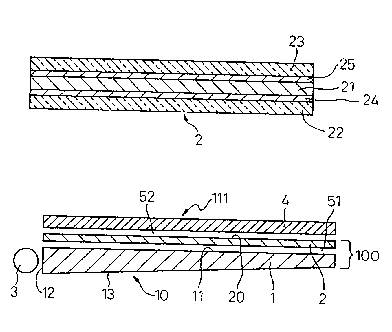
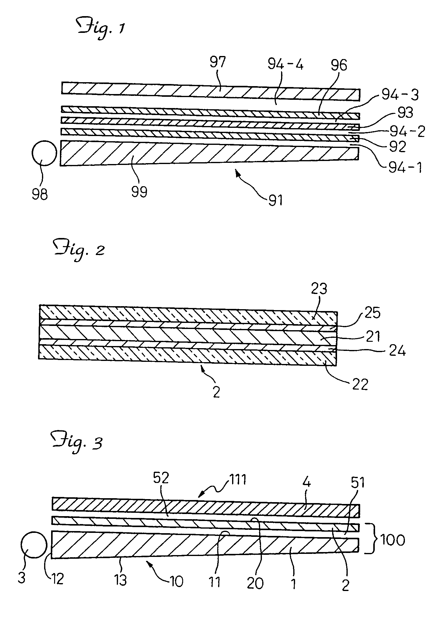
[0064]An optical laminated body was made in the following manner. As a polarizing layer, a reflection type polarizing film (thickness: 130 μm) was used. As first and second transparent films, an embossed type diffusive film Yupiron™ FEM M01 (thickness: 130 μm, haze: 79%) manufactured by Mitsubishi Engineering Plastic Co. was used.

[0065]The above polarizing film was a multi-layer type dielectric reflection film. A first polymer layer of a first dielectric unit containing the polarizing film was monoaxially stretched, while a second polymer layer of a second dielectric unit was not stretched. In the case of the first polymer layer, the direction intersecting perpendicularly to the stretching direction is a transmission axis and the stretching direction is a reflection axis.

[0066]A transmittance to light having a wavelength of 550 nm in the transmission axis of the polarizing film was 85% and the average transmittance in the region ranging from 400 to 800 nm was about 85%. The transmit...

example 2

[0075]An area luminescence equipment of this example was made in the same manner as in Example 1, except that one diffusive plate (the same diffusive plate as that used in Example 1), which is not contacted closely with the surface light source and optical laminated body, was used. Brightness was measured in the same manner as in Example 1, and was 336 cd / cm2. A diffusing point of the light guiding plate was not visually recognized from the liquid crystal surface of the area luminescence equipment of this example. The results of the visual property of the area luminescence equipment of the example are shown in Table 1 below.

[0076]

TABLE 1Visual angle in the case of using no lens film(reported in degrees):Example 1Example 2Comparative Example 1No diffusiveLowerUpper / lowerplatediffusive filmdiffuse filmsHorizontal595358directionPerpendicular494951direction

example 3

[0077]An area luminescence equipment of this example was made in the same manner as in Example 1, except that one lens film having a plurality of parallel linear prism lens was disposed between the optical laminated body and surface light source. The brightness measured in the same manner as in Example 1 was 455 cd / cm2.

[0078]In this example, the lens film was disposed such that the prism surface was contacted with the optical laminated body and that the lens film was not optically contacted with the light guiding plate of the surface light plate and optical laminated body. The lens film was a brightness-increasing film “BEF II 90 / 50” manufactured by 3M Co., and the lens film was disposed such that the longitudinal direction of the prism perpendicularly intersected a back-light fluorescent tube.


PUM

PropertyMeasurementUnit
reflectanceaaaaaaaaaa

Abstract

Lighting devices are disclosed that include optical laminated bodies. An exemplary optical laminated body includes a polarizing layer, a first transparent film disposed closely to a front surface of the polarizing layer and a second transparent film disposed closely to a back surface of the polarizing layer. The polarizing layer includes a reflective polarizing film, and both of the first transparent film and the second transparent film are diffusive films. The lighting devices further include a light source supplying light to the optical laminated body through a light entry surface of the first transparent film of the optical laminated body and a lens film disposed between the light source and the optical laminated body. The lighting device provides diffused-polarized light emitted from a light emitting surface of the second transparent film of the laminated body.

Description

FIELD OF THE INVENTION[0001]The present invention relates to area luminescence equipment such as light display equipment and also relates to lighting equipment such as back light equipment including back light equipment made of an optical laminated body, used for forming such area luminescence equipment. In other aspects, the invention relates to brightness-increasing films for improving the brightness of the area luminescence equipment in, for example, liquid display equipment.BACKGROUND OF THE INVENTION[0002]So-called brightness-increasing films improve the brightness of area luminescence equipment such as liquid display equipment. FIG. 1 shows one example of such an area luminescence equipment.[0003]In the example shown in FIG. 1, light from a surface light source 91 is supplied to a lower diffusive plate 92 through an air layer 94-1, and light transmitted to the lower diffusive plate 92 is diffused / emitted and then supplied to an optical film 93 through an air layer 94-2. Light ...

Claims


Application Information

Patent Timeline
Patent Type & Authority Patents(United States)
IPC IPC(8): F21V8/00
CPCG02B6/0043G02B6/0056
Inventor TOYOOKA, KAZUHIKO
Owner 3M INNOVATIVE PROPERTIES CO
Why Eureka
Try Eureka