Air foam pump with shifting air piston

a technology of air foam pump and air piston, which is applied in the direction of liquid transfer devices, single-unit apparatuses, instruments, etc., can solve the problem that the typical foaming liquid trigger sprayer cannot produce more dense foam, and achieve the effect of reducing the number of components, reducing the manufacturing cost of the dispenser, and eliminating the cost of the valv

Inactive Publication Date: 2005-01-11
SILGAN DISPENSING SYST CORP
View PDF45 Cites 79 Cited by
  • Summary
  • Abstract
  • Description
  • Claims
  • Application Information

AI Technical Summary

Benefits of technology

The manually operated foaming liquid dispenser of the present invention has a novel and simplified construction with a reduced number of component parts from that of prior art dispensers that pump both air and liquid in generating a foam discharged from the dispenser. The novel construction of the foaming liquid dispenser eliminates a valve that controls the flow of air into the air pump chamber of the dispenser, thereby eliminating the cost of the valve and reducing the manufacturing costs of the dispenser. In addition, the manually operated foaming liquid dispenser of the invention has a more simplified construction than that of other prior art foaming liquid dispensers. The more simplified construction of the dispenser also results in a reduction in manufacturing costs. In addition, the novel construction of the foaming liquid dispenser vents the interior of the air pump chamber to the exterior environment of the dispenser immediately upon upward movement of the pump plunger. This ensures that the air pump chamber is vented with air even when the user of the dispenser quickly reciprocates the pump plunger in the pump housing without allowing the pump plunger to return to its fully extended position relative to the pump housing.
Thus, the foaming liquid dispenser of the invention enables mixing of air and liquid pumped into the dispenser discharge passage to generate a thick foam discharged by the dispenser while eliminating a valve required by prior art dispensers to vent air to the air pump chamber. The elimination of the valve results in a reduction of manufacturing costs. The simplified construction of the foaming dispenser with its reduced number of component parts also reduces the manufacturing cost of the dispenser. In addition, the assembly of the air piston on the pump plunger that enables limited axial movement between the air piston and the pump plunger vents the interior of the air pump chamber promptly on upward movement of the pump plunger. This ensures that the air pump chamber is vented with air even when a user of the dispenser quickly reciprocates the pump plunger in the pump housing without allowing the pump plunger to return to its fully extended position relative to the pump housing.

Problems solved by technology

However, the typical foaming liquid trigger sprayer cannot produce a more dense foam, such as that of shaving cream.

Method used


Image

  • Air foam pump with shifting air piston
  • Air foam pump with shifting air piston
  • Air foam pump with shifting air piston

Examples


Embodiment Construction

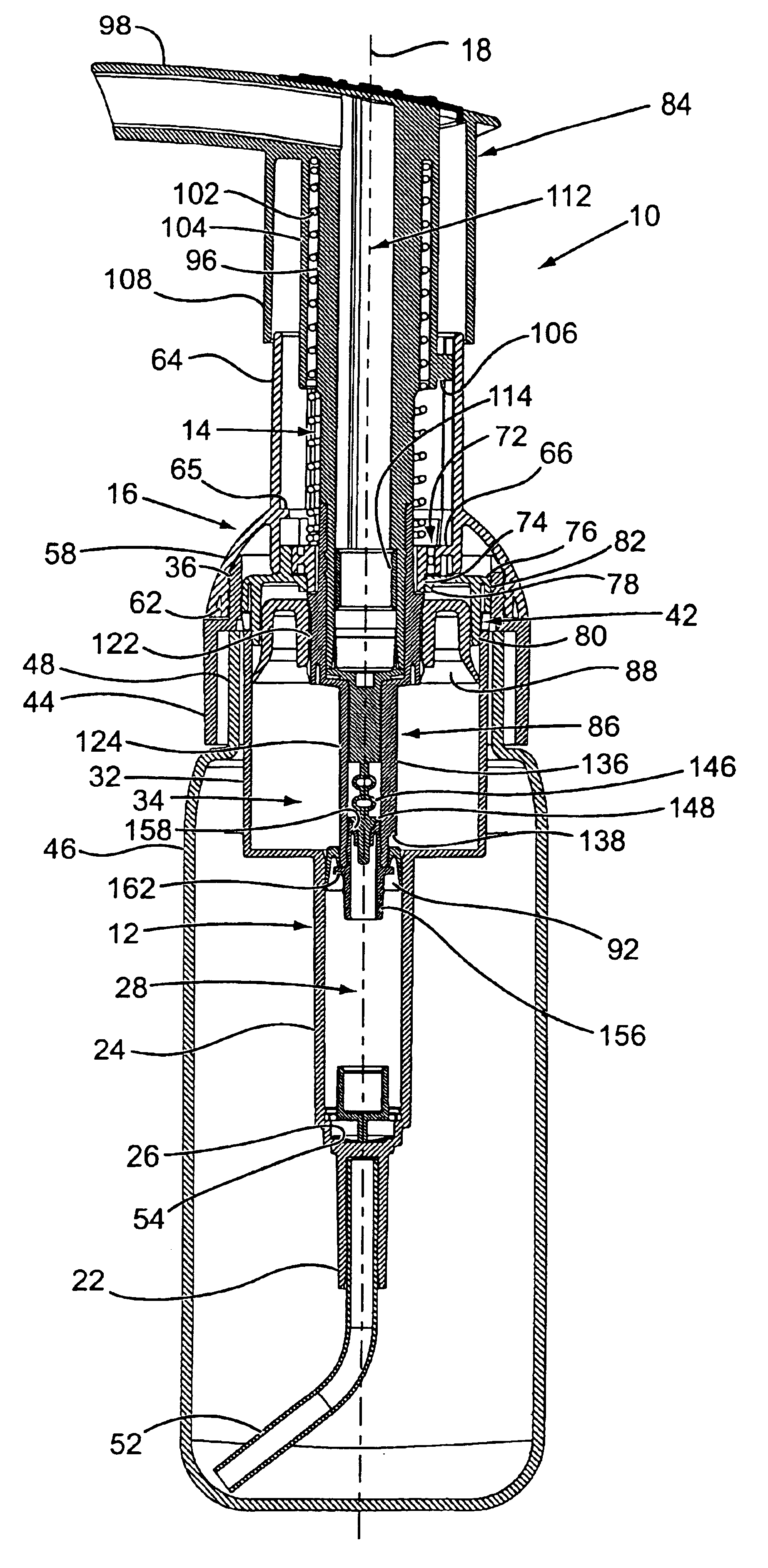
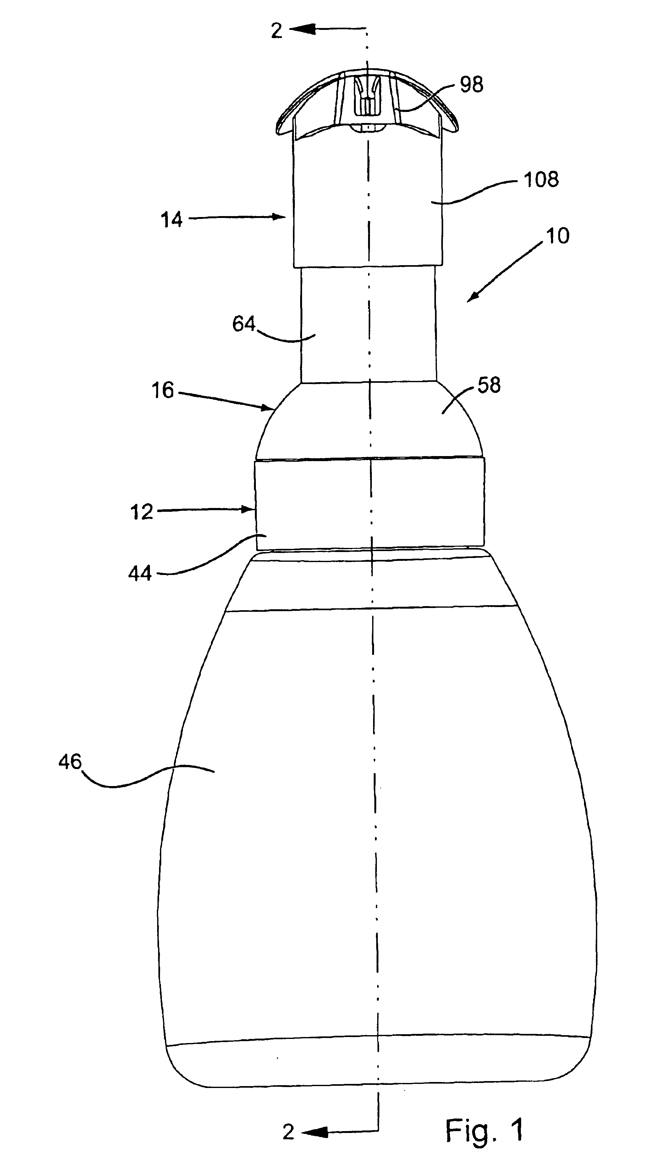
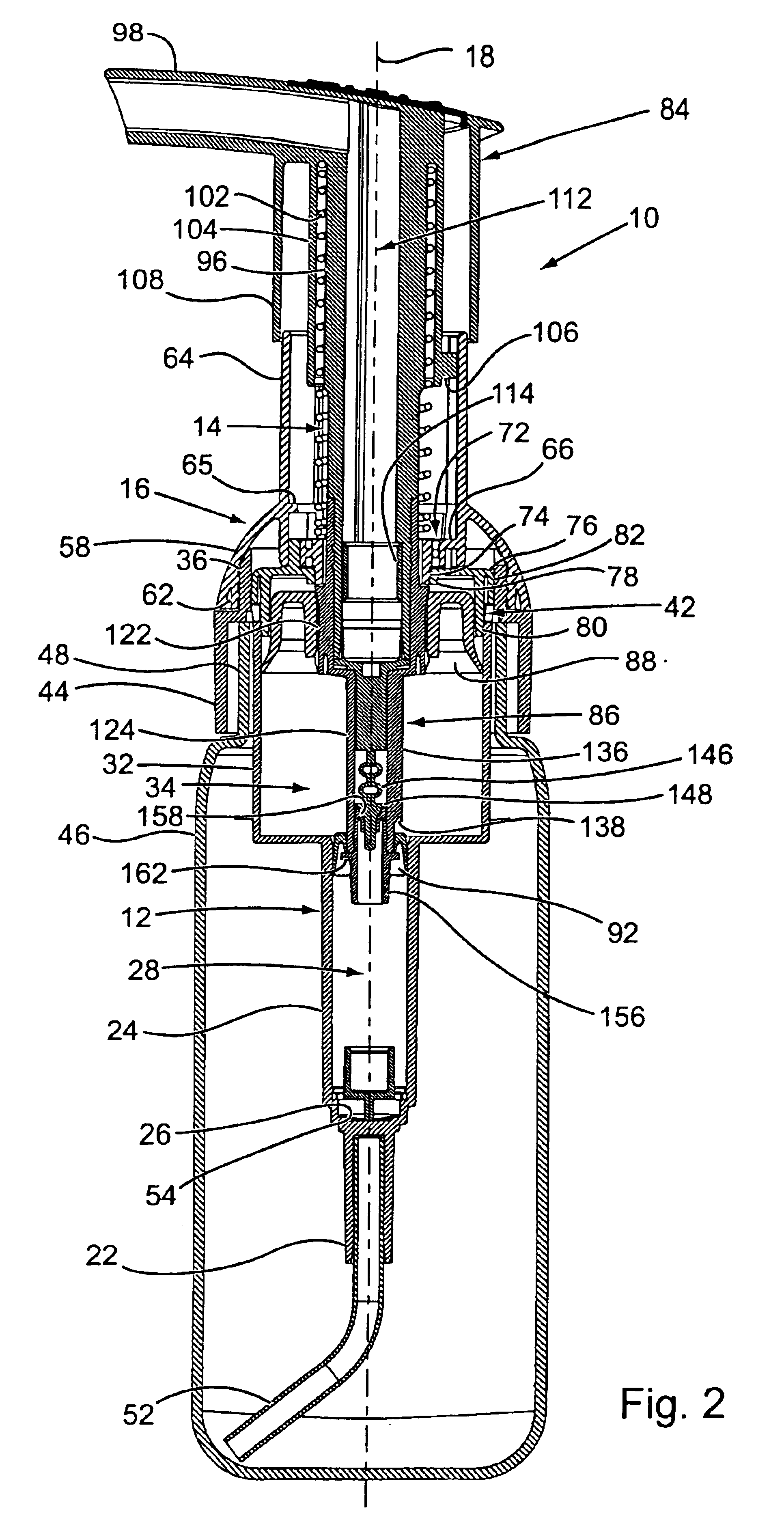
The foaming liquid dispenser 10 of the present invention is similar to the types of dispensers known in the prior art as lotion dispensers. These types of dispensers are typically operated by connecting the dispenser to the neck of a bottle container containing a liquid to be dispensed and by orienting the dispenser and the container vertically upright. In the description of the foaming liquid dispenser of the invention to follow, the terms “top” and “bottom”, “upper” and “lower”, or similar related terms will be used to describe the component parts of the dispenser and their relative positions. These terms are only used because the dispenser is typically oriented vertically upright when using the dispenser. The terms should not be interpreted as limiting.

The liquid foaming dispenser 10 shown in FIGS. 1, 2, and 4 is basically comprised of a pump housing 12, a pump plunger 14 and a snap ring 16 that connects the pump housing and pump plunger together. The materials employed in constr...


PUM


Abstract

A manually operated liquid foaming dispenser is attached to a bottle of liquid and pumps and mixes both the liquid and air to create a foam from the liquid and to dispense the foam. The dispenser includes a pump housing containing an air pump chamber and a liquid pump chamber, and a pump plunger that is manually reciprocated in both the air pump chamber and the liquid pump chamber. An air piston and a liquid piston are mounted on the plunger and are reciprocated by the plunger in the respective air pump chamber and liquid pump chamber. The air piston is mounted on the pump plunger for relative movement of the air piston on the plunger that enables an interior volume of the air pump chamber to be vented to an exterior environment of the dispenser on manual reciprocation of the pump plunger.

Description

BACKGROUND OF THE INVENTION(1) Field of the InventionThe present invention pertains to a manually operated liquid foaming dispenser. Specifically, the invention pertains to a manually operated pump that is attached to the top of a bottle of liquid and that pumps and mixes both the liquid and air to create a foam from the liquid and dispense the foam. The dispenser includes a pump housing containing an air pump chamber and a liquid pump chamber, and a pump plunger that is manually reciprocated in both the air pump chamber and the liquid pump chamber. An air piston and a liquid piston are mounted on the plunger and are reciprocated by the plunger in the respective air pump chamber and liquid pump chamber.(2) Description of the Related ArtThere are various different types of manually operated liquid dispensers that pump liquid from containers attached to the dispensers and generate a foam from the liquid that is discharged from the dispensers. A familiar example of these types of foam ...

Claims


Application Information

Patent Timeline
Patent Type & Authority Patents(United States)
IPC IPC(8): B05B11/00G01F11/02
CPCB05B11/3074G01F11/028B05B11/3087B05B11/1074B05B11/1087
Inventor FOSTER, DONALD D.NELSON, PHILIP L.
Owner SILGAN DISPENSING SYST CORP
Why Eureka
Try Eureka