Inverter topology for utility-interactive distributed generation sources

a distributed generation source and utility-interactive technology, applied in the field of inverters, can solve the problems of limiting the power level to relatively low levels, reducing the overall efficiency of the system, and being impractical compared to other inverter technologies, so as to reduce the number of parts, reduce the cost, and maximize the interaction

Inactive Publication Date: 2005-08-18
ADVANCED ENERGY CONVERSION
View PDF14 Cites 81 Cited by
  • Summary
  • Abstract
  • Description
  • Claims
  • Application Information

AI Technical Summary

Benefits of technology

[0018] The present invention provides an improved inverter topology for use with distributed generation sources. In particular, distributed generation sources, such as solar photovoltaic (PV) cells that produce direct current (dc), require an inverter to convert the dc into alternating current (ac) in order to deliver energy to an ac utility. The disclosed inverter topology of the present invention maximizes the interaction between cascaded conversion stages to reduce the number of parts, reduce the cost, improve the efficiency and improve the reliability of the inverter topology.

Problems solved by technology

This approach is based on a bidirectional flyback converter, thereby limiting it to relatively low power levels, typically 1 kW and under.
Above about 1 kW the flyback converter becomes impractical compared to other inverter technologies.
The use of the boost converter is blamed for the relatively low overall efficiency of the system.
Further, it will be appreciated that using resonant conversion within the inverter system tends to increase cost and lower efficiency since the resonant conversion process increases switch and transformer currents.
In this implementation the transformer is large and heavy because it operates at the ac utility frequency.
This use of the transformer for intermediate energy storage tends to increase the voltage and current stress on the semiconductor switches.
In view of the foregoing description of the prior art relative to inverter topologies for an ac utility interface, it will be appreciated that these inverter topologies contain one or more of the following deficiencies: reliance on a low frequency isolation transformer that is large and heavy; reliance on an isolation transformer that must store magnetic energy (this approach is impractical for applications that must support more than about 1 kW of power flow); reliance on resonant converter subsections that tend to increase component stress and can be difficult to control over wide ranges of load; reliance on converter stages that accomplish a specific task, but do so by effectively working against another stage of the topology (e.g., a buck converter stage cascaded with a boost converter stage).

Method used


Image

  • Inverter topology for utility-interactive distributed generation sources
  • Inverter topology for utility-interactive distributed generation sources
  • Inverter topology for utility-interactive distributed generation sources

Examples


Embodiment Construction

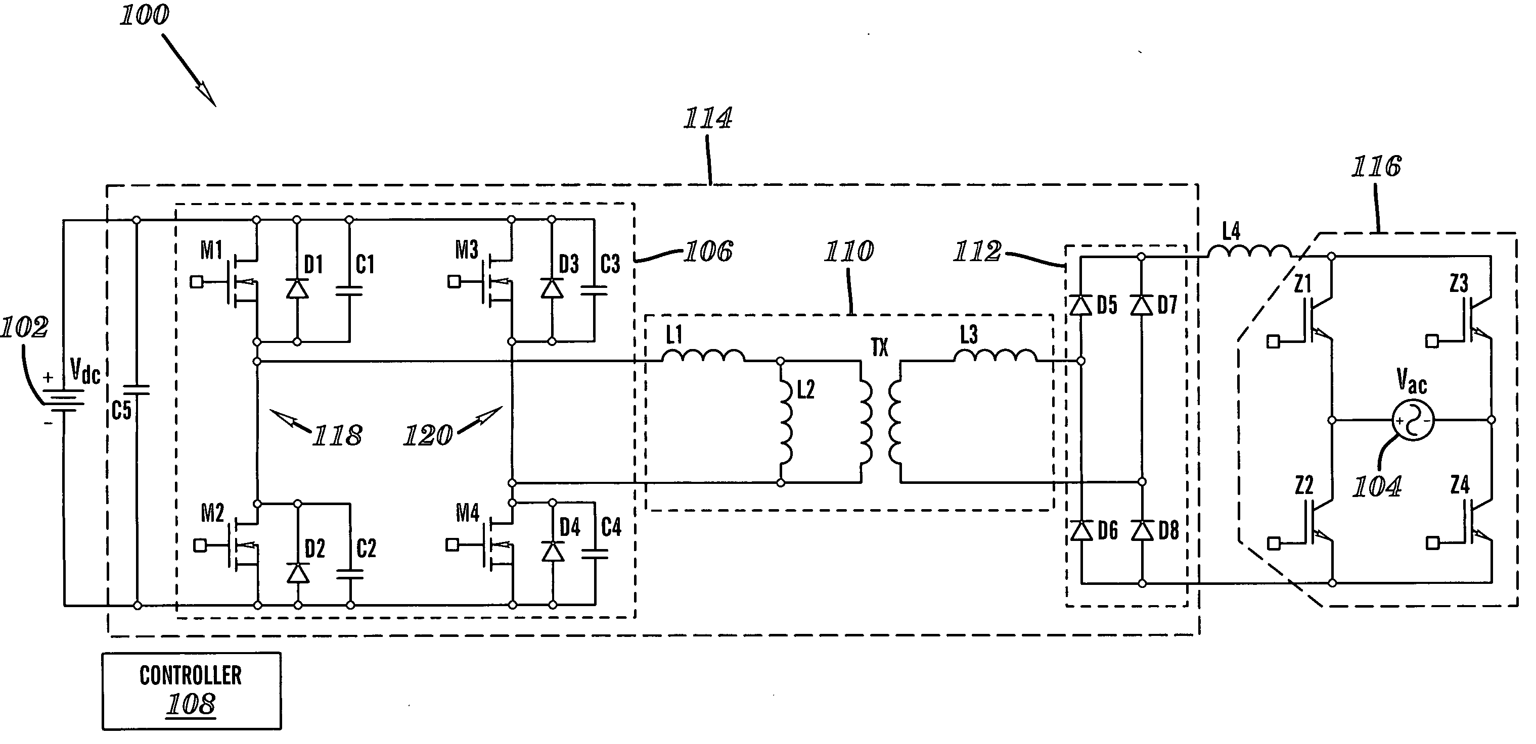
[0033]FIG. 6 illustrates an improved inverter system 100 in accordance with the present invention. In FIG. 6, Vdc 102 represents the source of direct current (dc). Vdc 102 may comprise one or more solar photovoltaic cells, a fuel cell, the rectified output of an alternator, a battery, a supercapacitor, etc. Vac 104 represents the alternating current (ac) utility. Switches M1-M4 on the input side form a phase-shifted input bridge 106, and may comprise metal oxide semiconductor field effect transistors (MOSFETs), a type of fully controllable semiconductor switch. Diodes D1-D4 and capacitors C1-C4 represent the body diodes and output capacitors of the MOSFETs M1-M4, respectively. That is, D1-D4 and C1-C4 are parasitic elements contained within the MOSFETs M1-M4. One skilled in the art will appreciate that other types of semiconductor switches can be used instead of MOSFETs, however, it may be necessary to use discrete physical components to emulate the parasitic elements (i.e., D1-D4 a...


PUM


Abstract

An inverter system for delivering energy from a source of direct current (dc) to an alternating current (ac) utility is provided. The inverter system comprises a dc/dc converter coupled to the source of dc for synthesizing a time-varying current from the dc, an output inductor coupled to the dc/dc converter, and an inverter coupled to the output inductor for supplying the time-varying current to the ac utility in phase with a voltage of the ac utility.

Description

BACKGROUND OF THE INVENTION [0001] 1. Technical Field [0002] The present invention relates generally to inverters for converting direct current (dc) to alternating current (ac). More specifically, the present invention provides an improved inverter topology for use with distributed generation sources such as solar photovoltaic (PV) cells. [0003] 2. Related Art [0004] Distributed generation sources that produce direct current (dc) require an inverter to convert the dc into alternating current (ac) where there is a desire or need to deliver that energy to an alternating current (ac) utility. Traditionally, distributed generation inverters, such as those used to deliver energy from solar photovoltaic (PV) cells to an ac utility, are comprised of multiple conversion stages, wherein each conversion stage has its own control. Taken collectively, the multiple conversion stages generally use a dc / dc converter that is responsible for preferentially loading the solar PV cells in order to maxi...

Claims


Application Information

Patent Timeline
Patent Type & Authority Applications(United States)
IPC IPC(8): H02M3/335H02M7/525
CPCH02M7/525H02M3/335
Inventor TORREY, DAVID A.KITTIRATSATCHA, SUPATBASHAW, TRAVIS B.CARPENTER, ROBERT T.
Owner ADVANCED ENERGY CONVERSION
Why Eureka
Try Eureka