

Oil removal from a stream of oil-separated sample droplets
a technology of oil removal and droplets, which is applied in the direction of liquid/fluent solid measurement, peptides, borehole/well accessories, etc., can solve the problems of hydrodynamic injection, lack of key features of “real” samples, and less study of oil removal between different modes, etc., to achieve complete oil removal, easy operation, and simple construction
- Summary
- Abstract
- Description
- Claims
- Application Information
AI Technical Summary
Benefits of technology
Problems solved by technology
Method used
Image

Examples
example 1
Deposition Device for MALDI
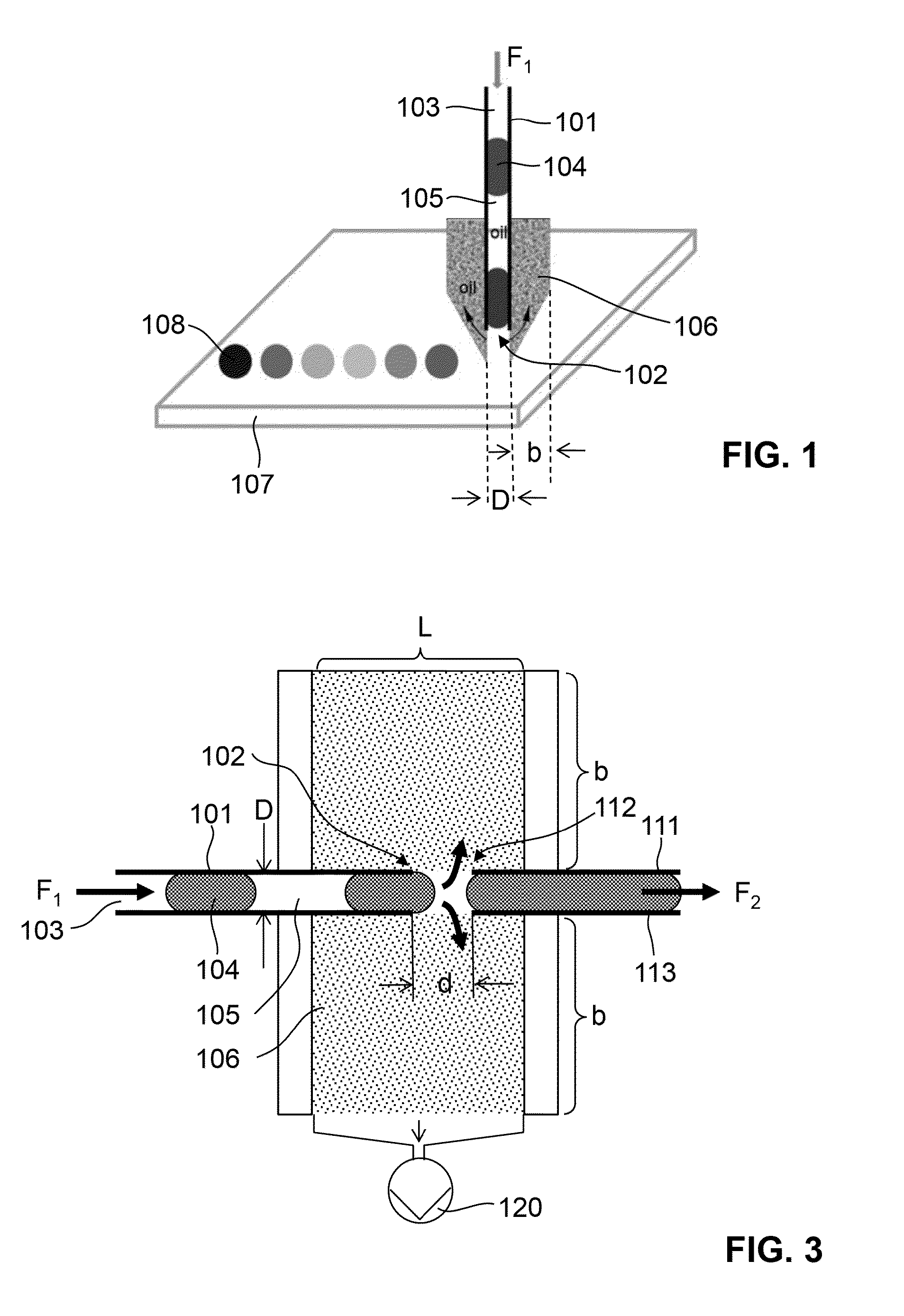
[0065]FIG. 1 illustrates a first embodiment of an oil removal device according to present invention (in the following also called a “droplet interface”) and of a corresponding method of oil removal. A sample delivery channel 101 is formed by a piece of tubing, e.g. by 200 μm I.D. PTFE tubing. The sample delivery channel 101 conducts a stream 103 of droplets 104 separated by an oil phase 105 to an outlet 102 along a flow direction F1. The outlet 102 is laterally surrounded by a porous, hydrophobic and oleophilic absorber element 106, e.g. in the form of porous PTFE. The absorber element 106 defines a three-dimensional, irregular array of pores. The absorber element 106 is arranged in a substantial tangential configuration relative to the flow direction F1. In particular, the absorber element has a central bore, in which the tubing forming the sample delivery channel 101 is received, and the bore wall forms an inner surface of the bore, which extends essenti...
example 2
Merging of Droplets after Oil Removal
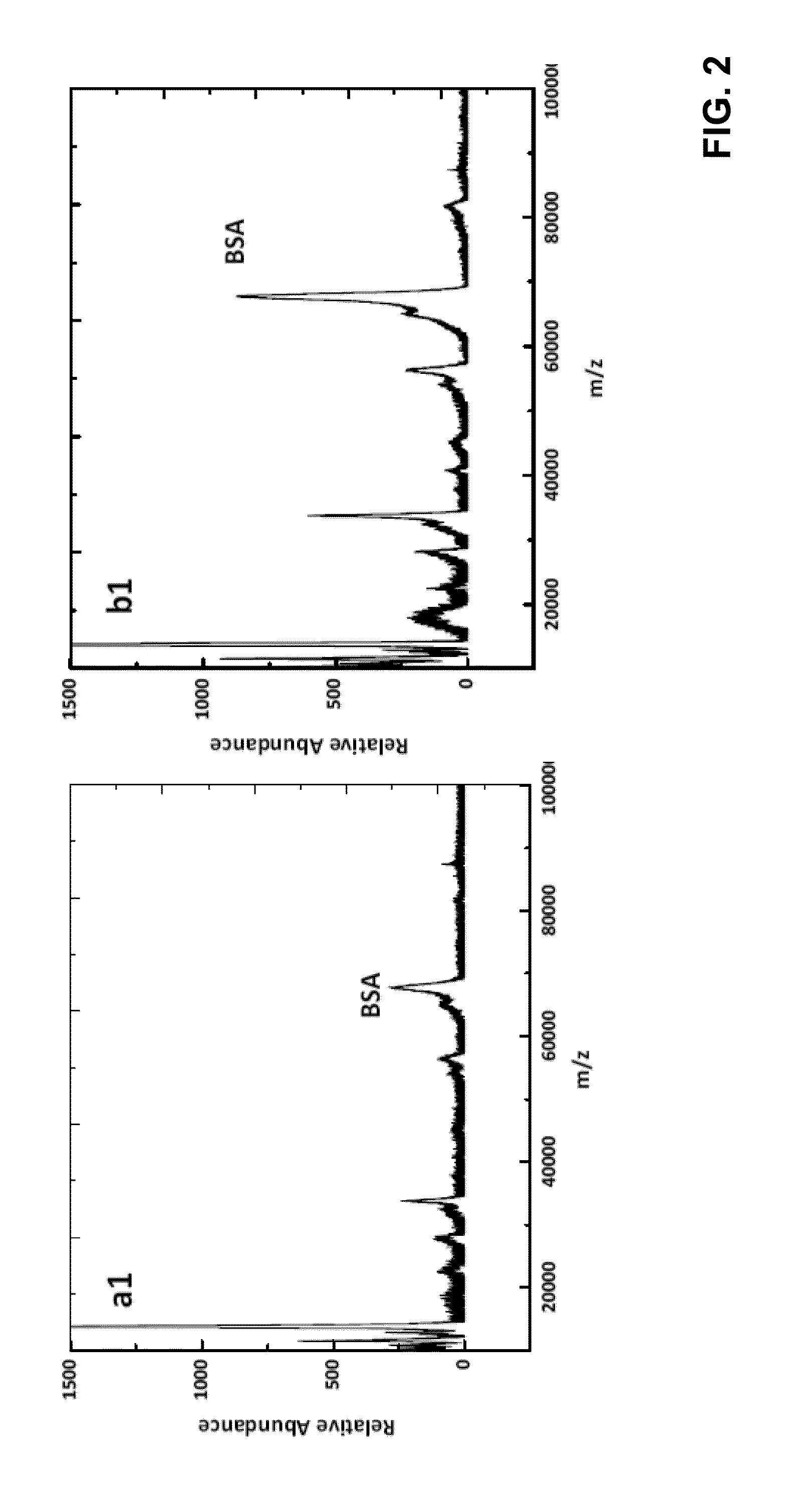
[0072]FIG. 2 illustrates a second embodiment of an oil removal device according to the present invention and of a corresponding method of oil removal. Parts having the same or similar functionality carry the same reference numbers as in FIG. 1. A stream 103 of oil-separated droplets 104 is transported to the outlet 102 of a sample delivery channel 101 formed by a first piece of PTFE tubing having an inner diameter D. The tubing protrudes into the upstream end of a central bore in a cylindrical, porous, hydrophobic and oleophilic absorber element 106. As in the first embodiment, the outlet 102 is surrounded by the absorber element 106, and the absorber element 106 is arranged in a substantial tangential configuration relative to the flow direction F1, the bore in the absorber element forming a continuation of the sample delivery channel. From the downstream end of the bore, a second piece of PTFE tubing forming an aqueous flow channel 111 protrude...
example 3
[0076]Electrophoresis is one of the most powerful and widely used tools in separation science and has progressed significantly since its original development in 1937. Currently many different methods exist to perform electrophoretic separations (e.g. CZE, CGE, MEMKC, ETC, etc.). More recently, capillary and chip-based, microfabricated electrophoresis methods (CE / MCE) have been developed to provide automated analysis in a broad range of applications, within the fields of genomics, proteomics, metabolomics, enzyme analysis and cellonics. The advantages of CE / MCE are manifested in their ability to deal with small volumes, provide for high separation efficiency, be automated and coupled with the other methodologies, such as liquid chromatography (LC) and mass spectroscopy (MS).
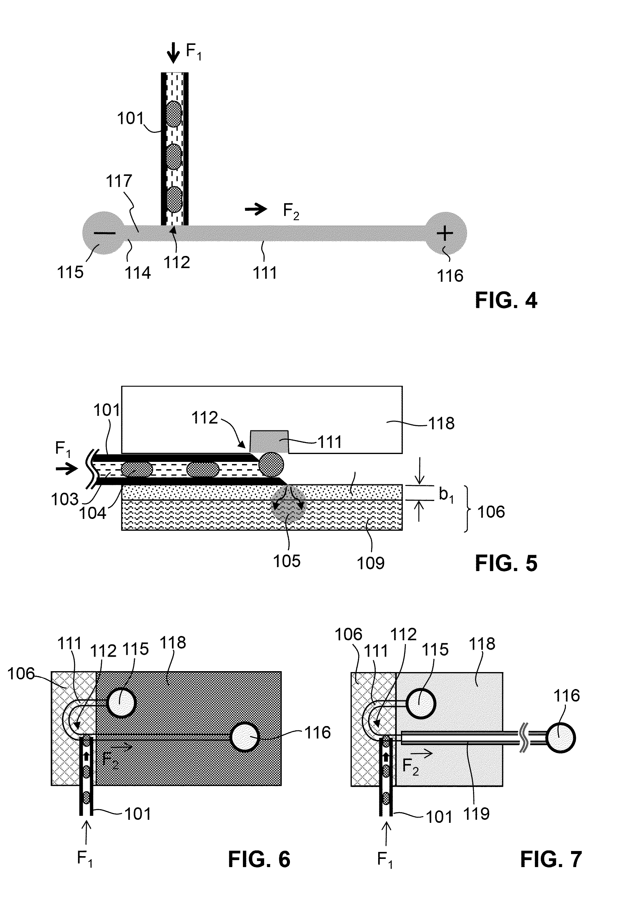
[0077]FIGS. 3-6 illustrate embodiments of an oil removal device according to the present invention that are particularly adapted for interfacing a stream of oil-separated droplets to a CE ...
PUM
| Property | Measurement | Unit |
|---|---|---|
| contact angle | aaaaa | aaaaa |
| contact angle | aaaaa | aaaaa |
| contact angle | aaaaa | aaaaa |
Abstract
Description
Claims
Application Information