Process cartridge and holding member

a technology of holding member and process cartridge, which is applied in the direction of electrographic process apparatus, instruments, optics, etc., can solve the problems of affecting the quality of the image, changing the charging capacity of the process cartridge, and occurrence of faulty images, so as to reduce the number of parts, simplify the construction, and the process is convenient.

Active Publication Date: 2005-02-03
CANON KK
View PDF32 Cites 80 Cited by
  • Summary
  • Abstract
  • Description
  • Claims
  • Application Information

AI Technical Summary

Benefits of technology

[0016] It is an object of the present invention to provide an inexpensive process cartridge simplified in construction.
[0017] It is an object of the present invention to provide an inexpensive process cartridge decreased in the number of parts.
[0018] It is an object of the present invention to...

Problems solved by technology

However, the charging apparatus of the above-described contact type, if left in contact with the photosensitive drum for a long period, has in some cases become such that a portion of a charging member (e.g. a charging roller) which contacts with the photosensitive drum causes permanent deformation, thus resulting in a change in its charging capability, and causing a faulty image such as uneven density.
Also, on the surface of the photosensitive drum, the photosensitive drum and the charging member frictionally contact with each other due to the vibration or the like during the transportation of the process cartridge, and a hysteresis remains as a charging memory, and this has sometimes led to the occurrence of a faulty image such as uneven density.
Also, when spacing apart is to be effected by the use of a solenoid, it is necessary to newly provide a complicate...

Method used


Image

  • Process cartridge and holding member
  • Process cartridge and holding member
  • Process cartridge and holding member

Examples


first embodiment

[0038] First Embodiment

[0039] [General Construction of a Color Image Forming Apparatus]

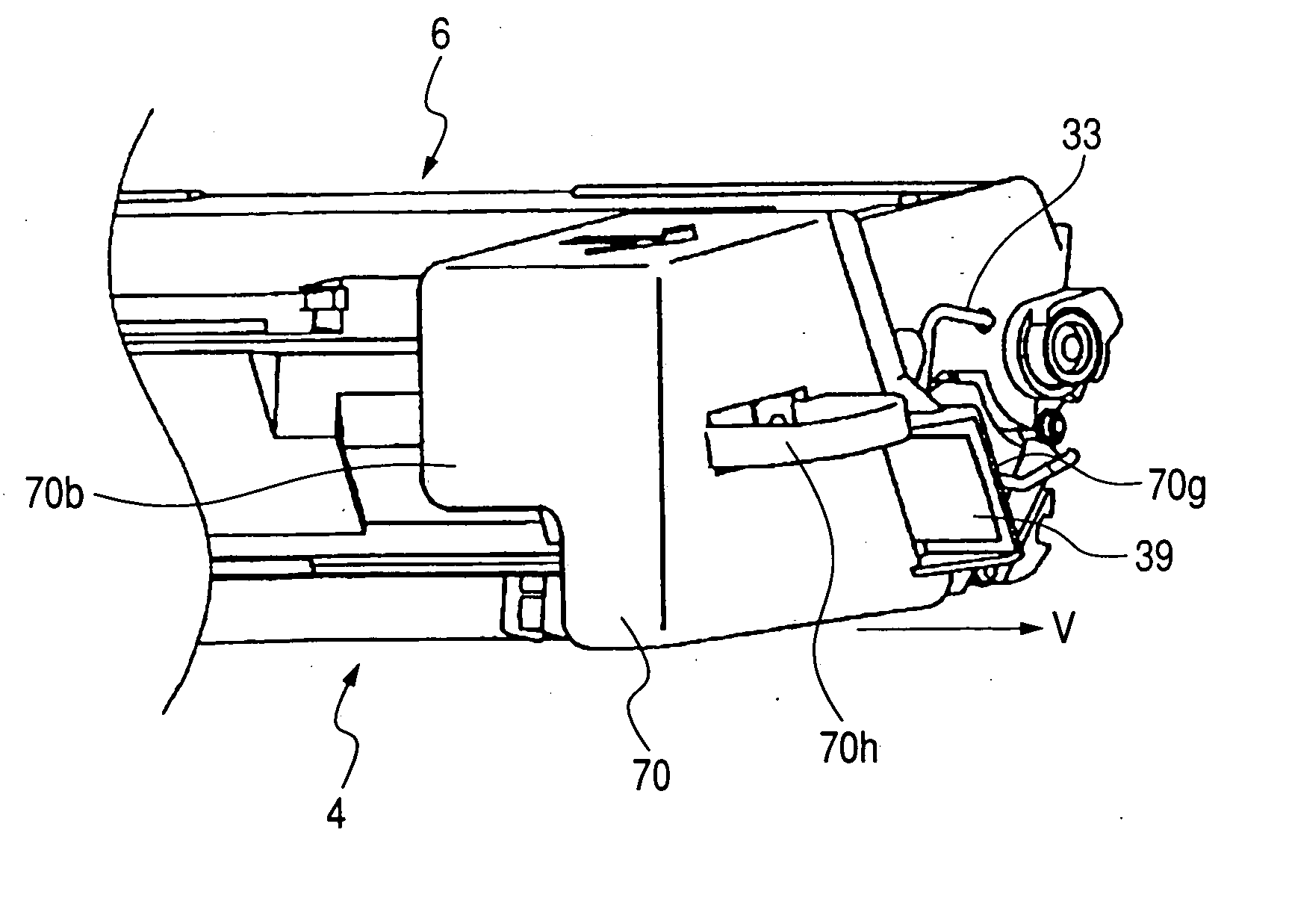
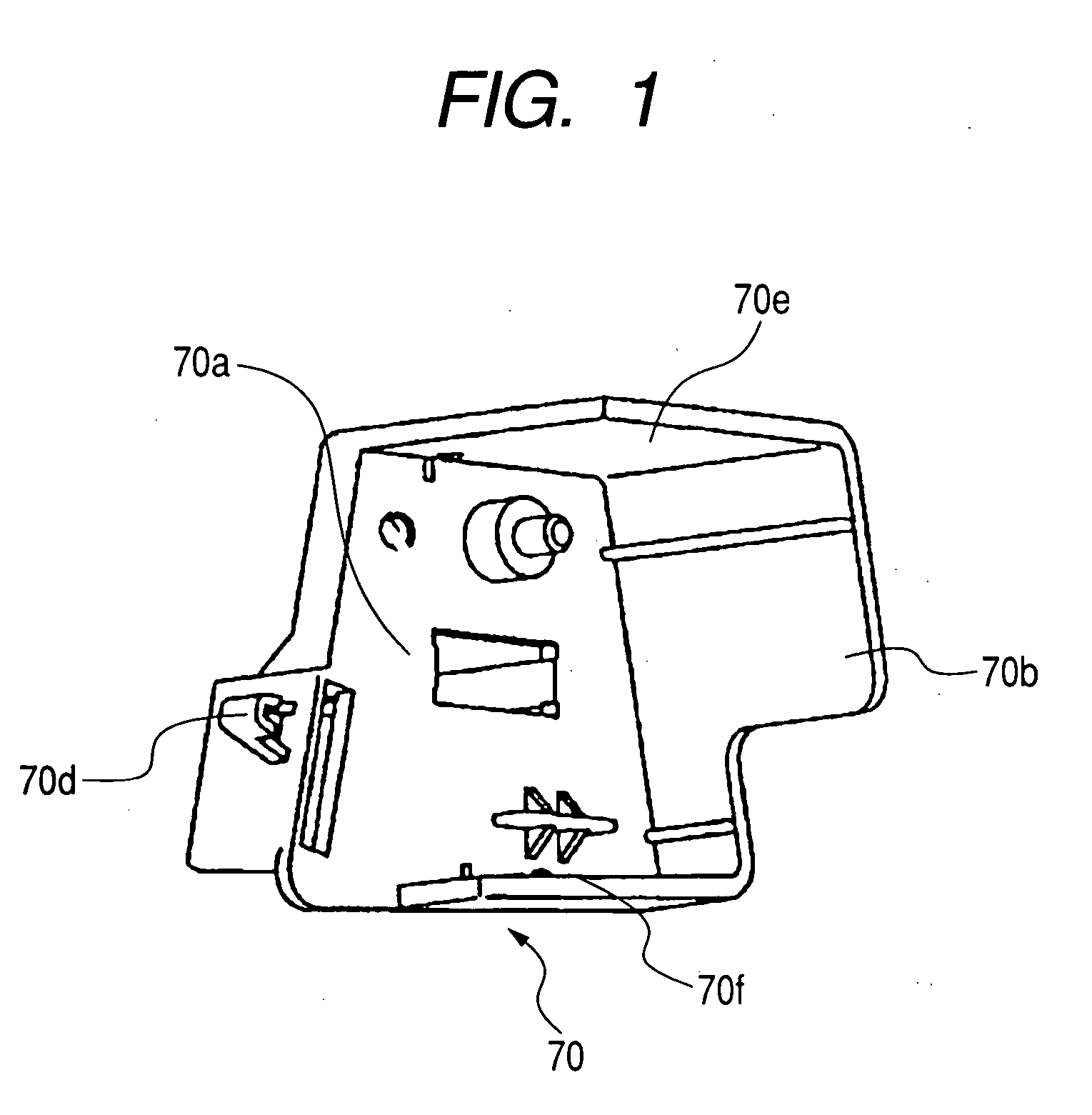
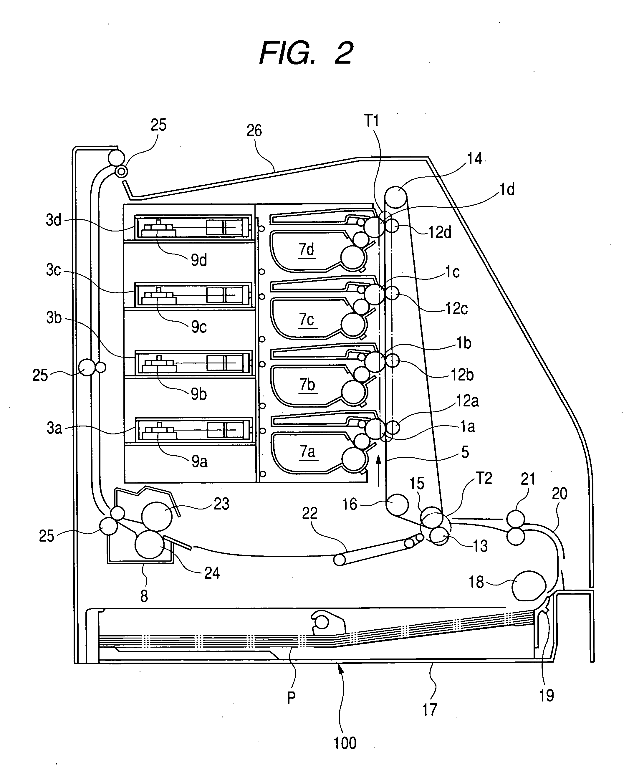
[0040] The general construction of a color electrophotographic image forming apparatus which is an example of an electrophotographic image forming apparatus will first be schematically described with reference to FIGS. 2 and 3. FIG. 2 is an illustration of the general construction of a full-color laser beam printer (hereinafter referred to as the printer) which is an embodiment of the color electrophotographic image forming apparatus, and FIG. 3 is an illustration of the general construction of a process cartridge used therein.

[0041] The printer 100, as shown in FIG. 2, is provided with an image forming portion having an electrophotographic photosensitive member (hereinafter referred to as the photosensitive drum) 1 (1a, 1b, 1c, 1d) which is an example of an image bearing member for each of yellow (Y), magenta (M), cyan (C) and black (Bk), and an intermediate transfer member 5 for holding thereon...

second embodiment

[0134] Second Embodiment

[0135] This embodiment is of the same construction as the first embodiment and duplicate description will be omitted. In the present embodiment, the space holding member of the first embodiment is provided with means for spacing the charging roller apart, in addition to the means for spacing the developing roller 40 apart. The present embodiment is characterized by this means for spacing the charging roller apart. The charging roller 23 in the present embodiment and the supporting construction of the charging roller will first be described with reference to FIG. 10. The charging roller 23 is constituted by a mandrel 23a and an electrically conductive rubber member 23b formed around it, and is urged against the photosensitive drum 1 by a pressure spring (biasing member) 132 through a bearing 23c. The charging roller 23 is rotatably supported on a charging roller bearing 131, which in turn is supported on a guide portion 133. The charging roller bearing 131 and...

third embodiment

[0146] Third Embodiment

[0147] This embodiment is characterized in that the spacing-apart member and the toner seal are connected together.

[0148] The construction of the present embodiment is substantially the same as the construction of the second embodiment, but as shown in FIG. 13, the present embodiment is of a construction in which the end portion of a toner seal 82 is attached to the toner seal attaching surface 123a of the space holding member 123. By adopting such a construction, when the user opens the toner seal, the spaced-apart state of the charging roller 23 and the spaced-apart state of the developing roller are released and therefore, the possibility of forgetting to pull out the charging moving member becomes null. Also, a construction for realizing this can be made very simple.


PUM


Abstract

In the present invention, when a space holding member for holding a photosensitive drum and a developing roller in a spaced-apart state acts on a process cartridge main body, the photosensitive drum and the developing roller are held in the spaced-apart state, and when the holding member is acting on a process cartridge, a storing medium provided in the process cartridge and the communication member of the storing medium are covered and hidden by the holding member. By the above-described construction, the spacing-apart of the developing roller and the protection of the storing medium can be effected by a member, and an improvement in usability and the curtailment of the number of parts can be achieved.

Description

BACKGROUND OF THE INVENTION [0001] 1. Field of the Invention [0002] The invention relates to a process cartridge for use in an electrophotographic image forming apparatus such as a copying machine or a printer adopting an electrophotographic process, and holding means, cover means and charging moving means for acting on a process cartridge main body. [0003] The electrophotographic image forming apparatus is an apparatus for forming an image on a recording material by the use of the electrophotographic process. Examples of the electrophotographic image forming apparatus include, for example, an electrophotographic copying machine, an electrophotographic printer (e.g. a laser beam printer, an LED printer or the like), a facsimile apparatus and a word processor or the like. [0004] Also, the process cartridge refers to charging means, developing means, cleaning means and an electrophotographic photosensitive member integrally made into a cartridge which is made detachably mountable with...

Claims


Application Information

Patent Timeline
IPC IPC(8): G03G21/18
CPCG03G21/1821G03G21/1885G03G2221/1861G03G2221/1654G03G2221/1823G03G2215/0119
Inventor TSUZUKI, MASATOMONITTANI, SUSUMUSUZUKI, TATSUYAYOKOMORI, KANJIMAESHIMA, HIDEKI
Owner CANON KK
Why Eureka
Try Eureka