Eureka AIR delivers breakthrough ideas for toughest innovation challenges, trusted by R&D personnel around the world.

Electric power steering device and method for assembling the same

a technology of electric power steering and electric motor, which is applied in the direction of instruments, force/torque/work measurement apparatus, transportation and packaging, etc., can solve the problems of difficult to secure the coaxiality of the output shaft b> and the lower shaft, and achieve the effect of effective prevention, and improving the assembling operability of the electric power steering devi

Active Publication Date: 2019-09-10
NSK LTD
View PDF20 Cites 2 Cited by
  • Summary
  • Abstract
  • Description
  • Claims
  • Application Information

AI Technical Summary

Benefits of technology

[0030]According to the above configuration, it is possible to prevent the torque detection sleeve and the torque detection concave-convex part from contacting each other upon the assembling, so that it is possible to improve the assembling operability.
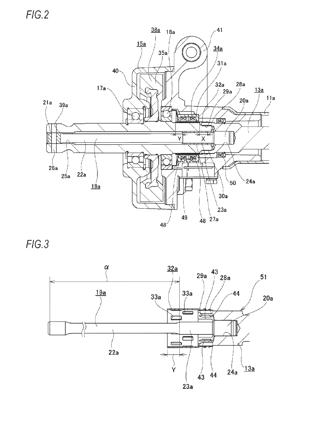
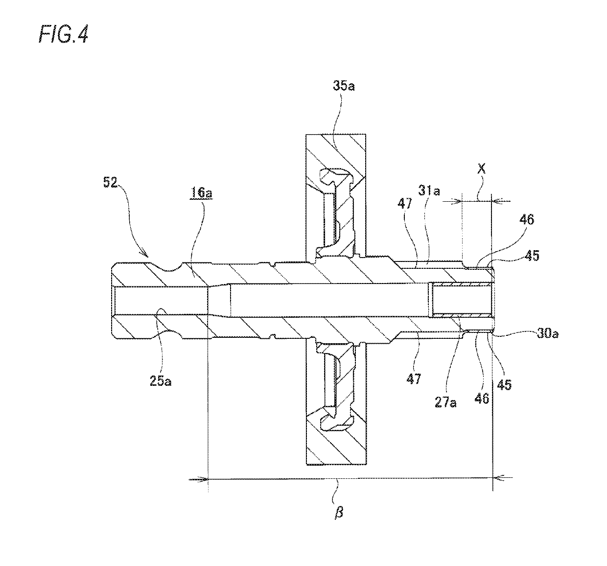
[0031]That is, in a completion state (assembling completed state) of the electric power steering device, the axial distance from the other axial end portion of the bush to the other axial end portion of the torque detection concave-convex part is larger than the axial distance from one axial end portion of the guide shaft part to one axial end portion of the torque detection sleeve.
[0032]For this reason, upon the assembling, in a state where the first coupling shaft part of the torsion bar is coupled to one rotary shaft of the input shaft and the output shaft arranged coaxially and the base end portion of the torque detection sleeve is externally fitted and fixed to the one rotary shaft, when inserting the second coupling shaft part of the torsion bar into the inner side of the other rotary shaft from the other axial end side and bringing the one rotary shaft and the other rotary shaft close to each other in the axial direction, it is possible to advance one axial end portion of the guide shaft part into the inner diameter side of the other axial end portion of the bush before one axial end portion of the torque detection sleeve is advanced into the outer diameter side of the torque detection concave-convex part.
[0033]Therefore, in a state where the coaxiality of the input shaft and the output shaft is secured by the torsion bar and the bush, it is possible to advance the torque detection sleeve into the outer diameter side of the torque detection concave-convex part.
[0034]As a result, it is possible to effectively prevent the torque detection sleeve and the torque detection concave-convex part from contacting each other. Thereby, it is possible to improve the assembling operability of the electric power steering device.
[0035]Also, according to the preferred embodiment, it is possible to internally fit the second coupling shaft part into the fitting hole formed in one axial end portion of the other rotary shaft with no interference before one axial end portion of the guide shaft part is advanced into the inner diameter side of the other axial end portion of the bush. Therefore, it is possible to secure the coaxiality of the input shaft and the output shaft to a certain degree by the fitting part between the second coupling shaft part and the fitting hole of the other rotary shaft. Accordingly, it is possible to smoothly advance one axial end portion of the guide shaft part into the inner diameter side of the other axial end portion of the bush.

Problems solved by technology

However, when assembling the electric power steering device of the conventional structure by the assembling method as described above, following problems may be caused.
Therefore, it is difficult to secure coaxiality of the output shaft 16 and the lower shaft 13.

Method used


Image

  • Electric power steering device and method for assembling the same
  • Electric power steering device and method for assembling the same
  • Electric power steering device and method for assembling the same

Examples


example of embodiment

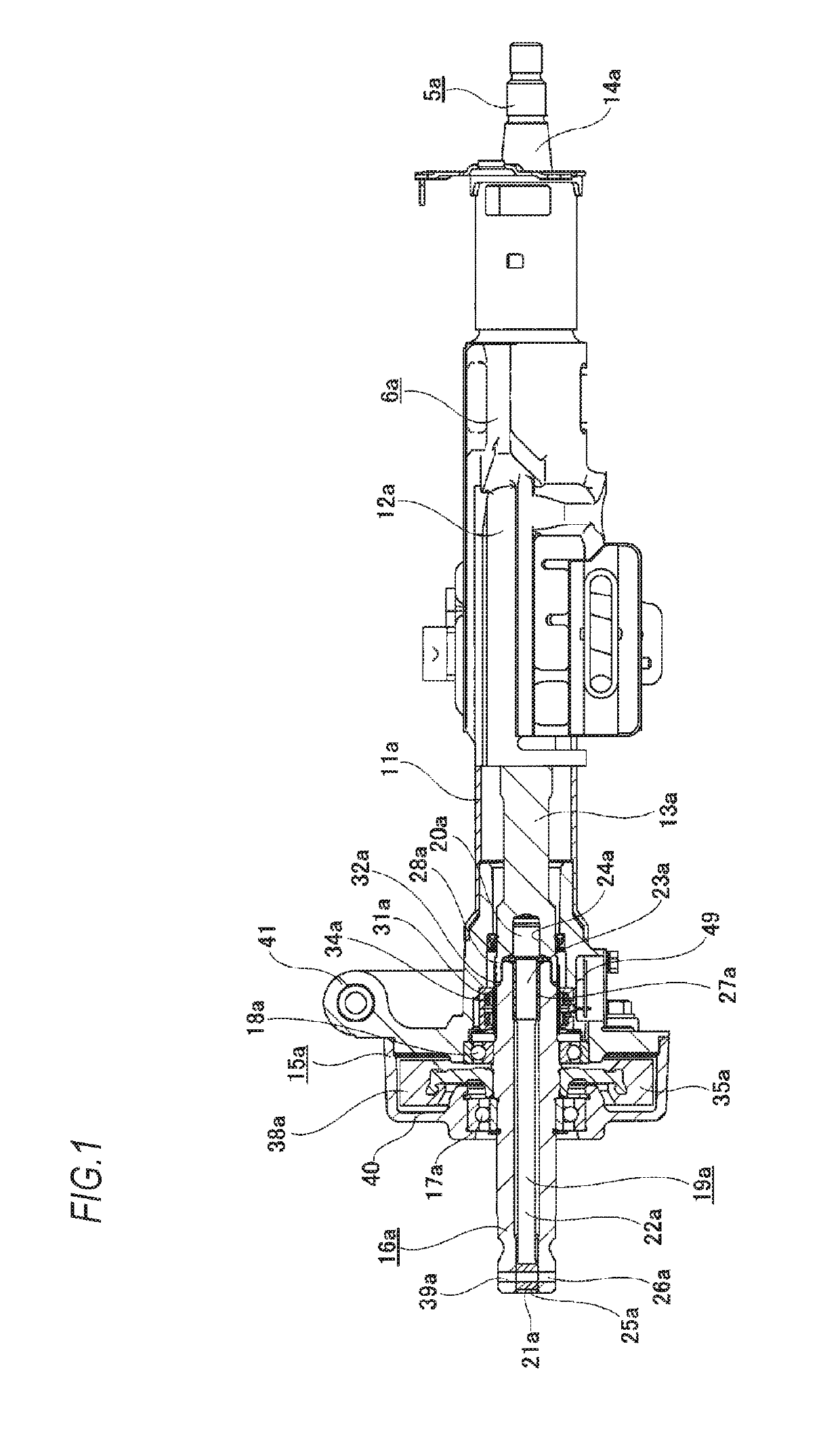
[0047]An example of an embodiment of the present invention will be described with reference to FIGS. 1 to 7. An electric power steering device of the example includes a steering column 6a, a steering shaft 5a, a housing 15a, an output shaft 16a, a torsion bar 19a, a bush 27a, a torque detection sleeve 32a, a torque detection coil unit 34a, a substrate 49, an electric motor 10 (refer to FIG. 8), and a worm reducer 38a.

[0048]The steering column 6a is configured by a cylindrical inner column 11a arranged at a front side and a cylindrical outer column 12a arranged at a rear side, which are combined to be expandable and contractible and are respectively formed of steel or light alloy such as aluminum alloy, and is supported to a vehicle body by a support bracket (not shown).

[0049]The steering shaft 5a is configured by spline fitting a lower shaft 13a arranged at a front side and formed of steel and an upper shaft 14a having a hollow shaft shape, arranged at a rear side and formed of ste...


PUM

PropertyMeasurementUnit
angleaaaaaaaaaa
outer diameteraaaaaaaaaa
diameteraaaaaaaaaa

Abstract

A first connecting part of a torsion bar is connected to a spline hole of a lower shaft, once the proximal end part of a torque-detecting sleeve has been externally fitted on and secured to a cylindrical part provided on the lower shaft, a second connecting shaft part of the torsion bar is inserted from the trailing end side into the inner side of an output shaft. When the lower shaft and the output shaft get closer to each other in the axial direction, the leading end part of a guide shaft part is advanced into the inner-diameter side of the trailing end part of a bush prior to the leading end part of the torque-detecting sleeve being advanced to the outer-diameter side of a part having protrusions and recesses for detecting torque.

Description

TECHNICAL FIELD[0001]The present invention relates to an improvement on an electric power steering device (EPS) to be used as an automobile steering device and configured to reduce a force, which is necessary to operate a steering wheel, by using an electric motor as an auxiliary power source, and a method for assembling the same.BACKGROUND ART[0002]FIGS. 8 to 10 illustrate an example of a conventional structure of an electric power steering device disclosed in Patent Document 1. The electric power steering device is configured to transmit rotation of a steering wheel 1 to an input shaft 3 of a steering gear unit 2 and to push and pull a pair of left and right tie-rods 4, 4 in association with rotation of the input shaft 3, thereby applying a steering angle to wheels. The steering wheel 1 is supported and fixed to a rear end portion of a steering shaft 5. The steering shaft 5 is rotatably supported to a cylindrical steering column 6 supported to a vehicle body with being inserted in...

Claims


Application Information

Patent Timeline
Patent Type & Authority Patents(United States)
IPC IPC(8): B62D5/04B62D6/10G01L5/22
CPCB62D6/10G01L5/221B62D5/0463B62D5/0409
Inventor NEMOTO, TATSUROU
Owner NSK LTD
Why Eureka
Eureka Blog
Learn More