
Energy storage apparatus

a technology of energy storage apparatus and a grip, which is applied in the direction of batteries, cell components, cell component details, etc., can solve the problems of poor assembling operability, difficult to carry the energy storage apparatus, and insufficient space between the grip and the lid, so as to improve the assembling operability and facilitate the holding

Active Publication Date: 2019-06-25
GS YUASA INT LTD
View PDF15 Cites 2 Cited by
  • Summary
  • Abstract
  • Description
  • Claims
  • Application Information

AI Technical Summary

Benefits of technology

The design enhances assembling efficiency and allows for stable and comfortable carrying of the energy storage apparatus, even when unbalanced, by enabling the handle to be mounted in advance and providing a sufficient sliding stroke for secure grip.

Problems solved by technology

Accordingly, the grip may not be assembled to the container in advance before energy storage devices are inserted into the container, and thus assembling operability may be poor.
In the energy storage apparatus disclosed in JP 10-40895 A, the grip is configured to be pulled out from the lid in a curved shape and hence, a sufficient space may not be secured between the grip and the lid.
Accordingly, it may be difficult to carry the energy storage apparatus by holding the grip well.
Particularly, a sliding direction of the grip and a lifting direction are orthogonal to each other and hence, such a configuration may not be applicable to carrying of an energy storage apparatus which is unbalanced in weight.

Method used


Image

  • Energy storage apparatus
  • Energy storage apparatus
  • Energy storage apparatus

Examples


Embodiment Construction

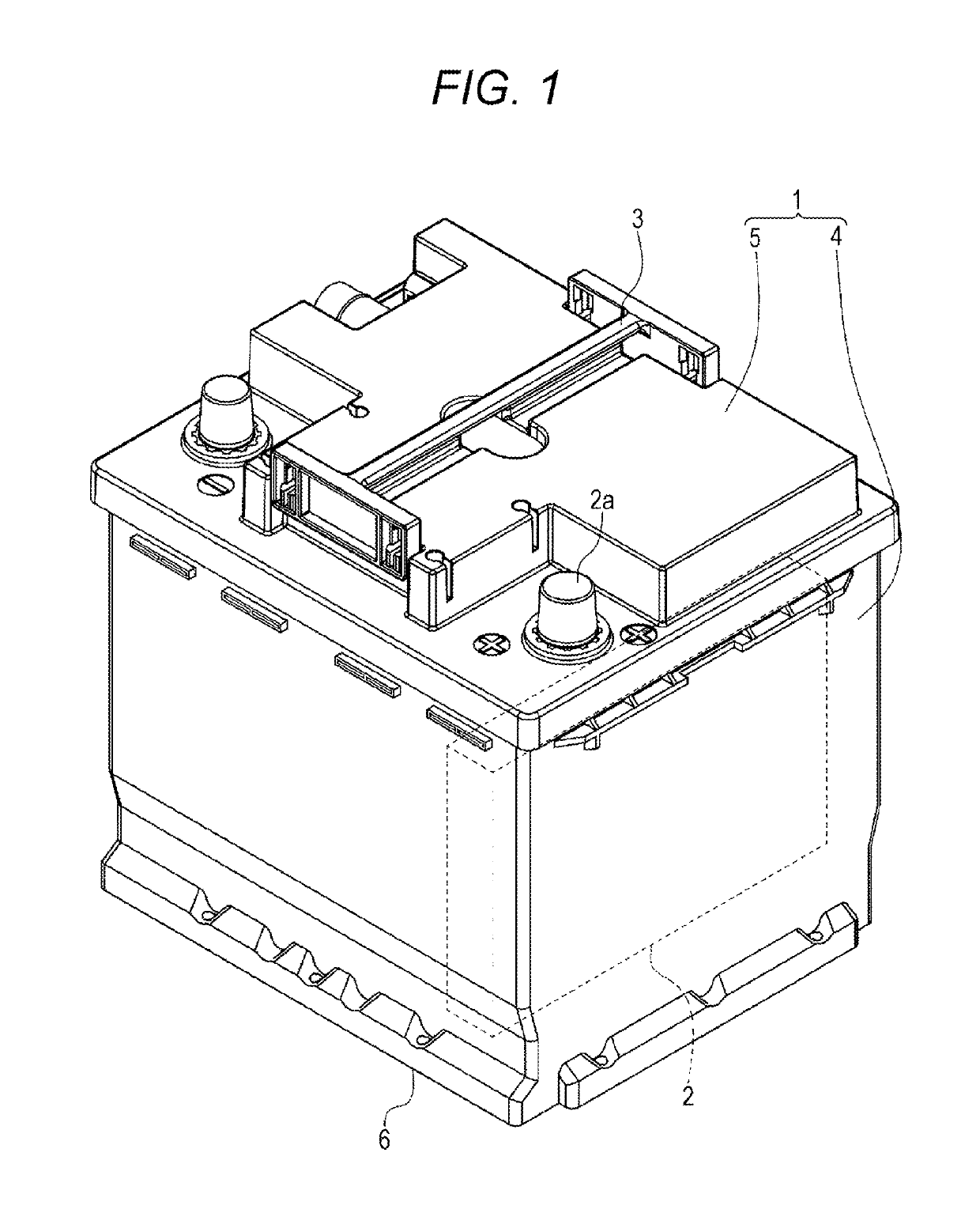
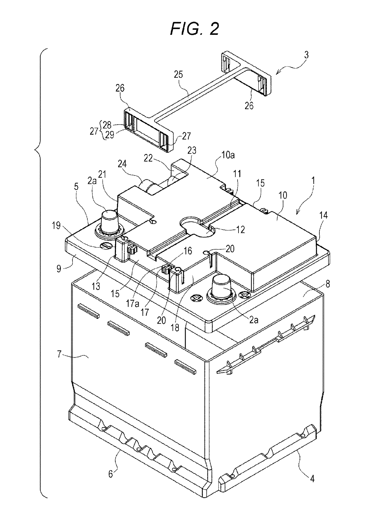
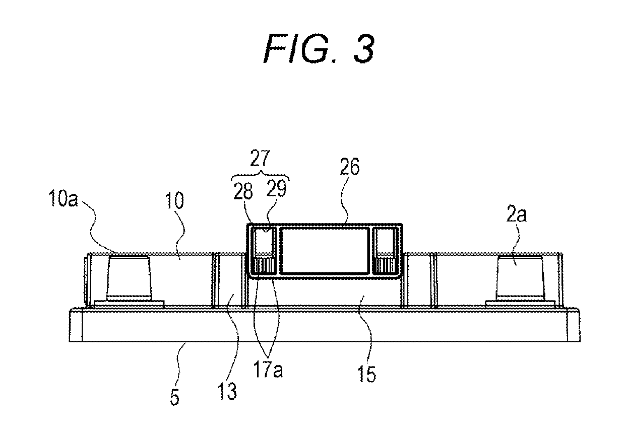
[0020]According to an aspect of the present invention, there is provided an energy storage apparatus which includes: an outer case formed of a body, and a lid body which covers an opening of the body; an energy storage device which is accommodated in the outer case; and a handle which is mounted on the lid body, wherein the lid body has a first surface, and a second surface which is disposed adjacently to the first surface, the handle is formed of a handle body extending from one end side toward the other end side, and slide portions which are respectively formed on both end sides of the handle body, the handle body is disposed on the first surface, and slide receiving portions which hold the slide portions in a slidable manner are formed on the second surface.

[0021]With such a configuration, when a user holds and lifts the handle body, the slide portions slide on the slide receiving portions, and the handle body is separated from the first surface of the lid body. The handle can be...


PUM

PropertyMeasurementUnit
distanceaaaaaaaaaa
widthaaaaaaaaaa
depthaaaaaaaaaa

Abstract

An energy storage apparatus includes: an outer case formed of a body, and a lid body which covers an opening of the body; an energy storage device which is accommodated in the outer case; and a handle which is mounted on the lid body. The lid body has a first surface, and a second surface which is disposed adjacently to the first surface. The handle is formed of a handle body extending from one end side toward the other end side, and slide portions which are respectively formed on both end sides of the handle body. The handle body is disposed on the first surface. Slide receiving portions which hold the slide portions in a slidable manner are formed on the second surface.

Description

CROSS-REFERENCE TO RELATED APPLICATIONS[0001]This application is based on Japanese Patent Application No. 2016-201213, filed on Oct. 12, 2016, the entire contents of which are hereby incorporated by reference.FIELD[0002]The present invention relates to an energy storage apparatus.BACKGROUND[0003]Conventionally, there has been known an energy storage apparatus where recessed portions are formed on upper portions of side surfaces of a container, and both end portions of a transverse member (hereinafter descried as a grip) are attached to the recessed portions in a vertically slidable manner (see JP 62-52850 A, for example).[0004]There has been also known an energy storage apparatus where a handle (a grip) is mounted in a recessed portion formed on an upper surface of a lid in a state where the handle can be pulled out in a curved shape from the recessed portion (see JP 10-40895 A, for example).[0005]However, in the energy storage apparatus disclosed in JP 62-52850 A, the grip is not a...

Claims


Application Information

Patent Timeline
Patent Type & Authority Patents(United States)
IPC IPC(8): H01M2/10H01G9/008H01M2/20H01G11/78H01M10/36H01M50/209H01M50/227H01M50/278H01M50/296H01M50/507
CPCH01M2/1005H01G9/008H01G11/78H01M2/1072H01M10/36H01M2/206Y02E60/13H01M2220/10H01M2220/20H01M50/227H01M50/296H01M50/278H01M50/507H01M50/209Y02E60/10H01M50/256
Inventor TONONISHI, MASAMITSU
Owner GS YUASA INT LTD
Learn More