Image processing method and apparatus

a technology of image processing and image, applied in the field of image processing methods and apparatuses, can solve the problems of troublesome user's exposure correction operation, difficult to appropriately determine the brightness of the image, and excessive brightness of the background portion of the main subject, so as to prevent the occurrence of gradation jump or color displacement, and improve the brightness distribution of the digital image to be processed

Inactive Publication Date: 2008-08-05
CANON KK
View PDF6 Cites 16 Cited by
  • Summary
  • Abstract
  • Description
  • Claims
  • Application Information

AI Technical Summary

Benefits of technology

[0013]An object of the present invention is to solve the above conventional problems, and moreover to prevent occurrence of gradation jump or color displacement even if a process for improving a brightness distribution of a digital image to be processed is performed.
[0015]Another object of the present invention is to prevent lowering of contrast in a low-frequency area of an image due to a process for improving a brightness distribution of a digital image to be processed.

Problems solved by technology

However, such an exposure correction operation is troublesome for a user, and moreover skill is required to appropriately set the exposure of the camera.
Besides, even if the exposure correction is appropriately performed with respect to the main subject, the background portion of the main subject adversely tends to become bright excessively.
In order to solve such a problem, it is necessary to obtain an image of appropriate brightness even in the backlight scene or the like that it is generally difficult to appropriately determine the brightness of the image.
However, in the above conventional methods, there is a problem that, in a case where the image data in which the improvement process has been performed to the brightness of the digital image to be processed cannot be fell within the range of a predetermined color space, a gradation jump and a color tone displacement (aberration) occur with respect to the color of the image data outside the color space because it is replaced with the color on the border area of the color space and the replaced color is then output.
Moreover, in the above conventional methods, there is a problem that, in the image data in which the improvement process has been performed to the brightness of the digital image to be processed, a contrast in the low-frequency area of the image deteriorates because a black level and a white level in the low-frequency area change, whereby the image becomes vague as a whole.

Method used


Image

  • Image processing method and apparatus
  • Image processing method and apparatus
  • Image processing method and apparatus

Examples


first embodiment

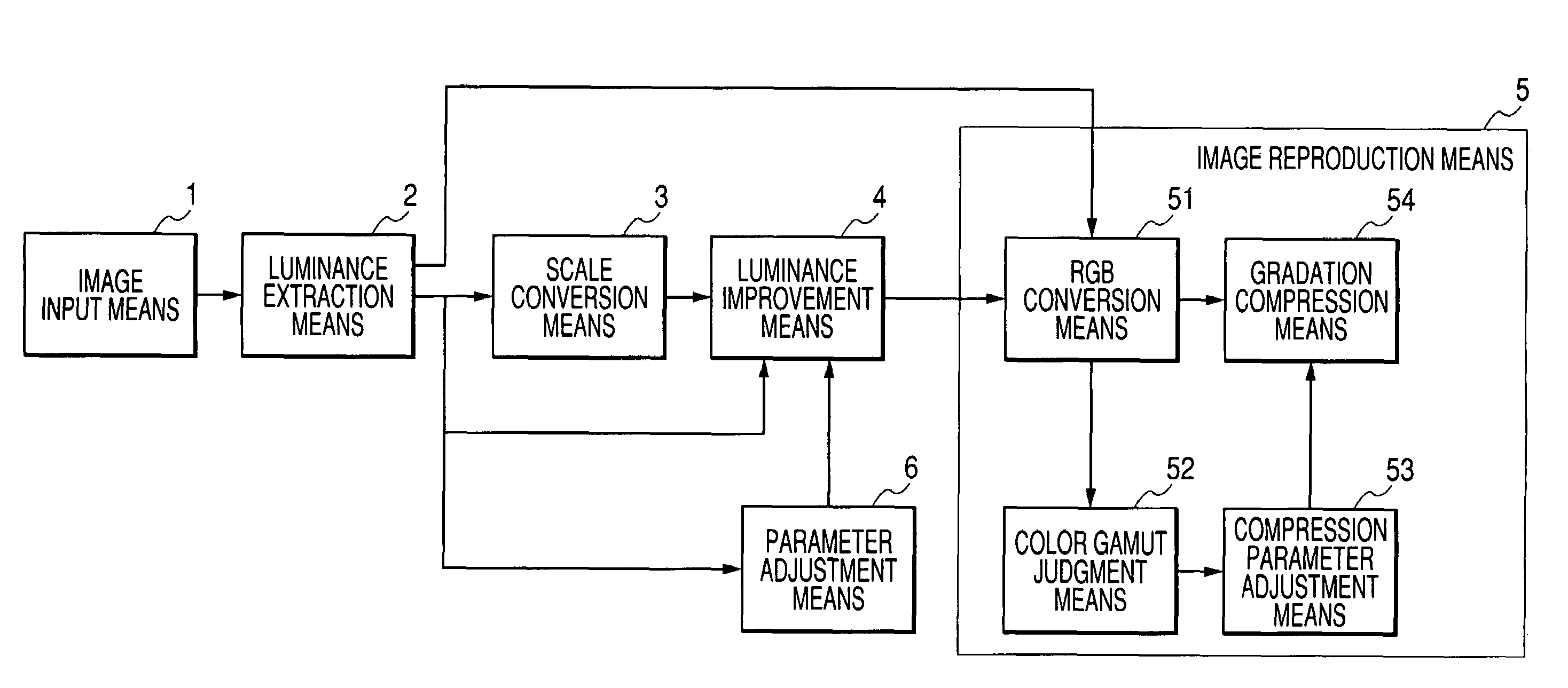
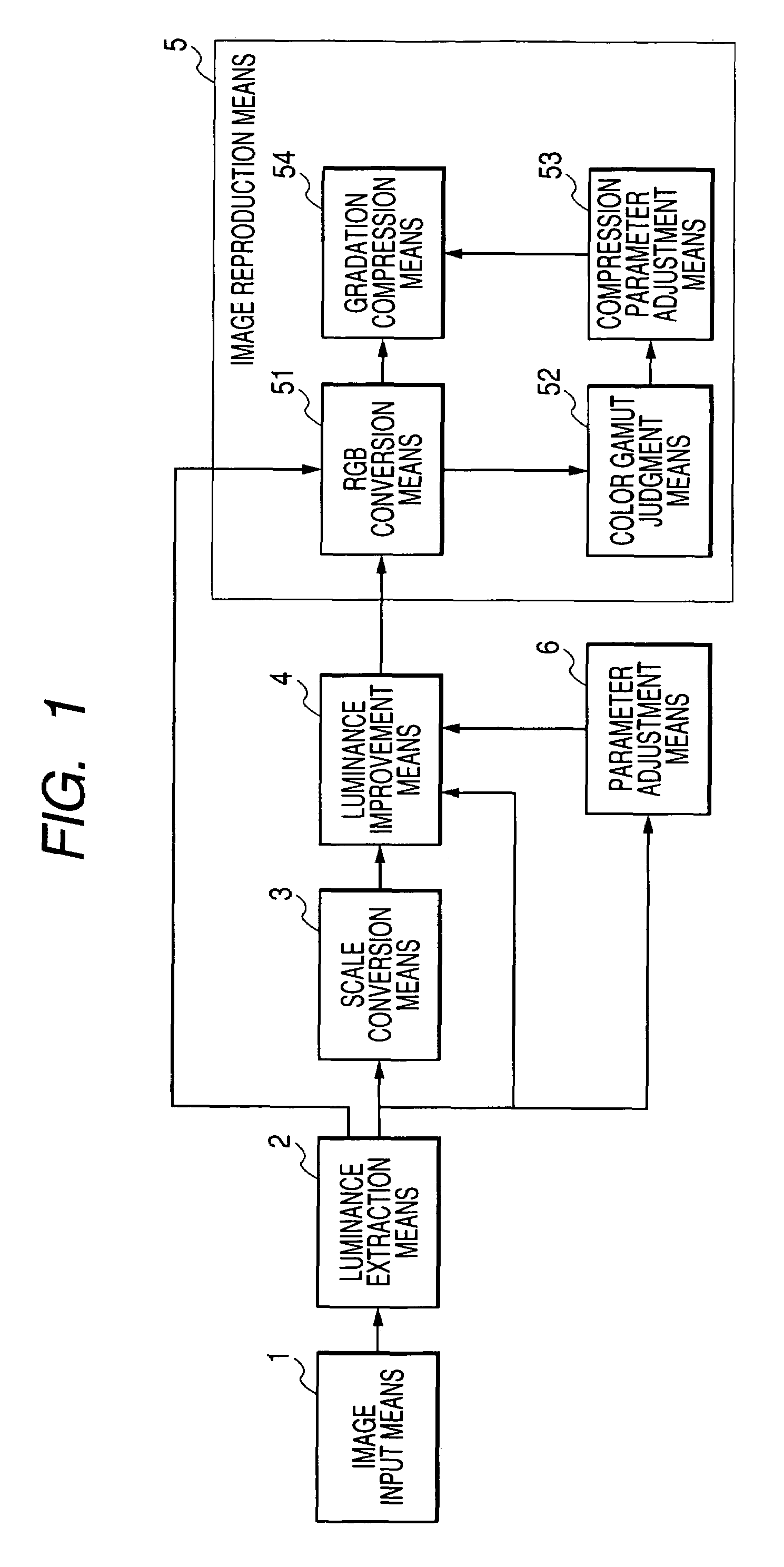
[0026]FIG. 1 shows the structure of an image processing system according to the present embodiment.

[0027]In FIG. 1, reference numeral 1 denotes an image input means for inputting digital image data (hereinafter, called image data) into the image processing system. For example, such the input means is constituted in a digital camera, a scanner or the like.

[0028]Reference numeral 2 denotes a luminance extraction means for extracting luminance components and color components from the image data which was input by the image input means 1. Reference numeral 3 denotes a scale conversion means for obtaining the distribution, on a relative large scale, of the luminance component of the image data which was output from the luminance extraction means 2. Reference numeral 4 denotes a luminance improvement means for improving the distribution of the luminance component of the image data by use of the luminance component of the image data which was output from the luminance extraction means 2 an...

second embodiment

[0083]FIG. 4 shows the structure of an image processing system according to the second embodiment. The same structures as those in the first embodiment are respectively denoted by the corresponding reference numerals same as those in the first embodiment, and the description thereof will be omitted.

[0084]In the first embodiment, in the case where the luminance improved result exceeds the color gamut, the gradation is compressed for the luminance improved result. On one hand, in the present embodiment, a parameter used in improving the luminance is changed, and the luminance is improved again.

[0085]In FIG. 4, reference numeral 5 denotes an image reproduction means for reconstituting image data by synthesizing the improved luminance component which was output from a luminance improvement means 4 with the color component which was output from a luminance extraction means 2. The image reproduction means 5 is composed of an RGB conversion means 51, a saturation judgment means 21 and an e...

third embodiment

[0096]FIG. 6 shows the structure of an image processing system according to the present embodiment.

[0097]In FIG. 6, reference numeral 1 denotes an image input means for inputting digital image data (hereinafter, called image data) into the image processing system. For example, such the input means is constituted in a digital camera, a scanner or the like.

[0098]Reference numeral 2 denotes a luminance extraction means for extracting luminance components and color components from the image data which was input by the image input means 1. Reference numeral 3 denotes a scale conversion means for obtaining the distribution, on a relative large scale, of the luminance component of the image data which was output from the luminance extraction means 2. Reference numeral 4 denotes a luminance improvement means for improving the distribution of the luminance component of the image data by using the luminance component of the image data which was output from the luminance extraction means 2 and...


PUM


Abstract

It aims to prevent occurrence of gradation jump or color displacement even if a process for improving a brightness distribution of a digital image to be processed is performed. An image processing method for achieving such prevention comprises: an extraction step of extracting a brightness component from image data; a scale conversion step of obtaining a distribution of the brightness component on relatively large scale; an improvement step of improving the brightness component distribution of the image data by using the brightness component and an output in the scale conversion step; and a gradation compression step of judging whether or not the image data reconstituted according to the improved brightness component distribution is within a predetermined color gamut, and, when it is judged that the reconstituted image data includes the image data outside the predetermined color gamut, of performing a gradation compression process.

Description

[0001]This application claims priorities from Japanese Patent Applications No. 2003-199121 and No. 2003-199123 both filed on Jul. 18, 2003, which are hereby incorporated by reference.BACKGROUND OF THE INVENTION[0002]1. Field of the Invention[0003]The present invention relates to image processing method and apparatus which improve a distribution of brightness of a digital image.[0004]2. Related Background Art[0005]Conventionally, as a method of taking a photograph of appropriate brightness, a method of measuring average luminance of a scene to be taken or photographed and then controlling shutter speed, a aperture value and the like based on the measured average luminance is known. Moreover, an exposure control method based on so-called evaluation photometry that a scene is first divided into predetermined areas, luminance of each of the divided areas is measured, the measured luminance is appropriately weighted with respect to each area, average luminance is then obtained based on t...

Claims


Application Information

Patent Timeline
Patent Type & Authority Patents(United States)
IPC IPC(8): G06K9/00G06K9/40G06T5/40
CPCG06T5/009G06T5/40G06T2207/10024
Inventor YANO, KOTARO
Owner CANON KK
Why Eureka
Try Eureka