Multilayer capacitor

a multi-layer capacitor and capacitor technology, applied in the field of multi-layer capacitors, can solve the problems of inability to increase degrading the high-frequency characteristics, and esr, and achieve the effects of increasing the width of the frequency band, low impedance, and high esr

Active Publication Date: 2008-12-16
MURATA MFG CO LTD
View PDF26 Cites 9 Cited by
  • Summary
  • Abstract
  • Description
  • Claims
  • Application Information

AI Technical Summary

Benefits of technology

[0009]To overcome the problems described above, preferred embodiments of the present invention provide a multilayer capacitor which provides a high ESR while providing a low ESL and also increases the width of a frequency band in which low impedance is obtained.

Problems solved by technology

H11-144996, an ESR (equivalent series resistance) also decreases with decreasing ESL, which results in steep frequency-impedance characteristics.
This causes degradation of high-frequency characteristics, as compared with the structure described in Japanese Unexamined Patent Application Publication No.
H11-144996 in terms of a frequency band in which low impedance can be obtained, and thus it is not possible to increase the width of the frequency band in which low impedance can be obtained.

Method used


Image

  • Multilayer capacitor
  • Multilayer capacitor
  • Multilayer capacitor

Examples


Embodiment Construction

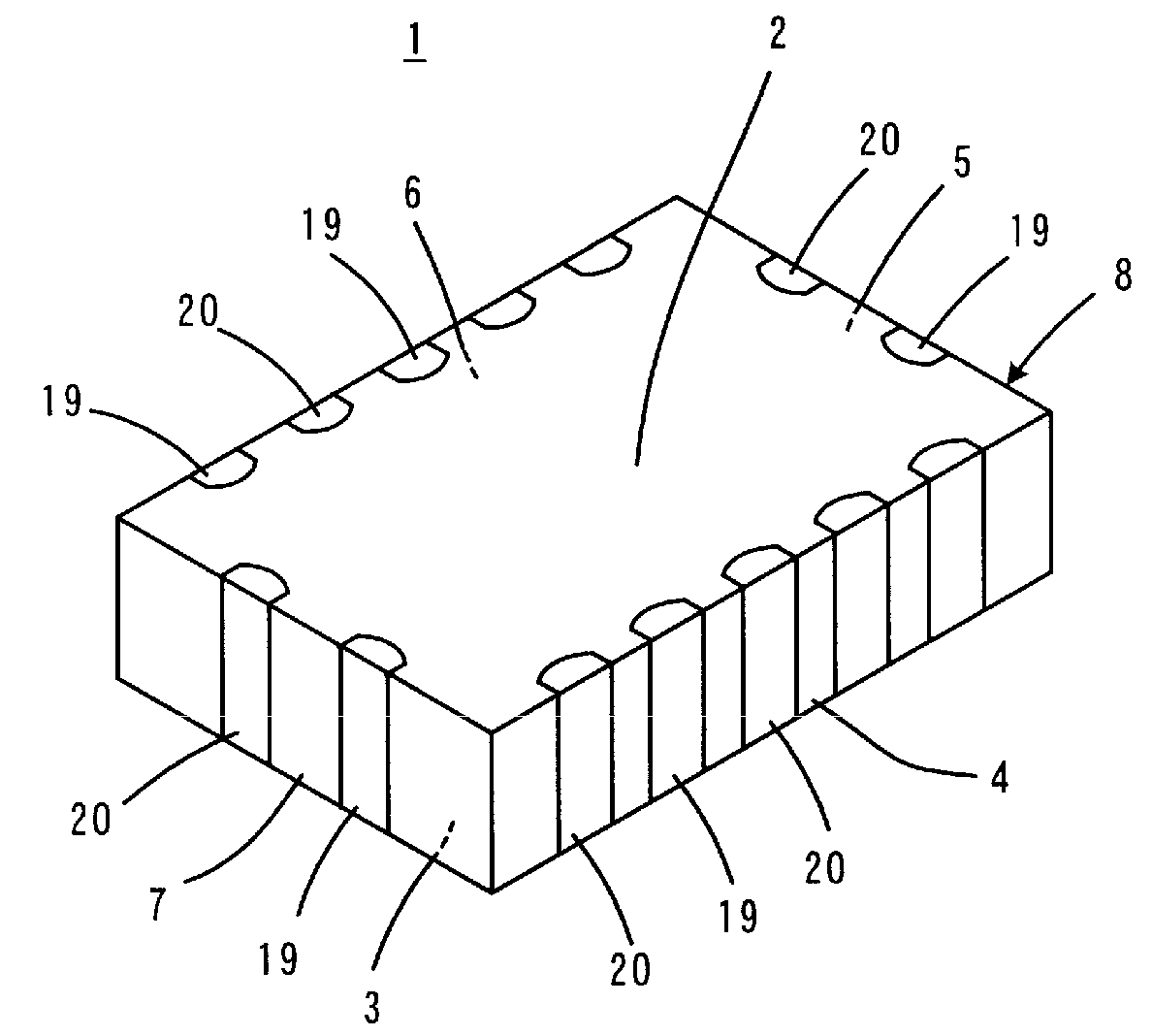
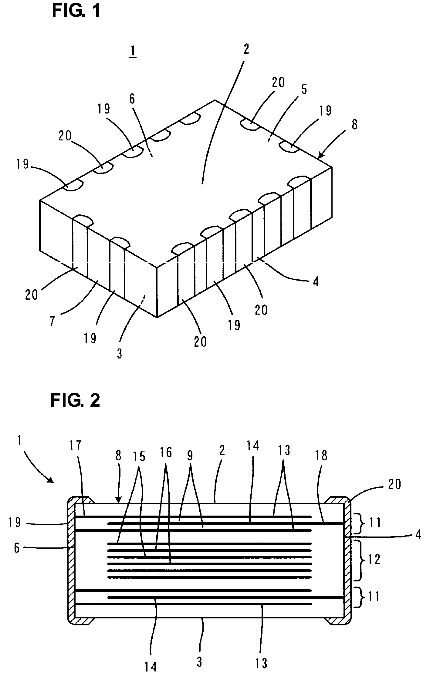
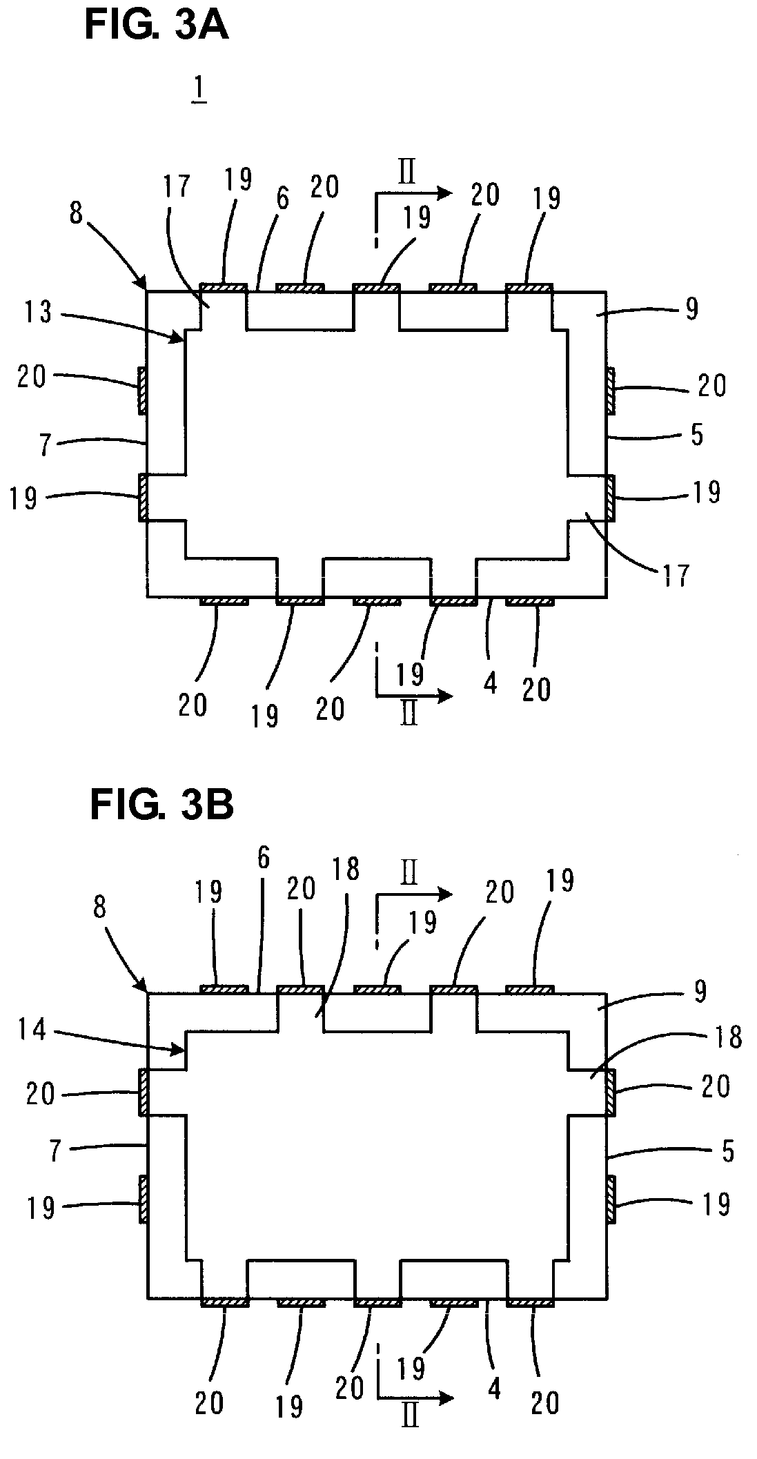
[0032]FIG. 1 to FIG. 4B show a multilayer capacitor 1 according to a preferred embodiment of the present invention. FIG. 1 is a perspective view showing the multilayer capacitor 1. FIG. 2 is an elevational view showing an internal structure of the multilayer capacitor 1. In FIG. 2, the multilayer capacitor 1 is shown in cross-section taken along lines II-II in FIG. 3A to FIG. 4B.

[0033]The multilayer capacitor 1 includes a substantially rectangular parallelepiped shaped capacitor body 8 having two opposing principal surfaces 2 and 3 and four side surfaces 4, 5, 6, and 7 connecting the principal surfaces 2 and 3. The capacitor body 8 has a layered structure composed of a plurality of laminated dielectric layers 9 which extend along the direction of the principal surfaces 2 and 3 and are made of, for example, a dielectric ceramic.

[0034]As shown in FIG. 2, the capacitor body 8 includes first and second capacitor portions 11 and 12. In this preferred embodiment, the first capacitor porti...


PUM

PropertyMeasurementUnit
capacitanceaaaaaaaaaa
widthaaaaaaaaaa
widthaaaaaaaaaa

Abstract

In a multilayer capacitor including a capacitor body, first capacitor portions and a second capacitor portion are arranged in the direction of lamination. While a resonant frequency of the first capacitor portions is set to be greater than a resonant frequency of the second capacitor portion so that the first capacitor portions contribute to low impedance, an ESR per layer of the second capacitor portion is set to be greater than an ESR per layer of the first capacitor portions so that the second capacitor portion contributes to high ESR. Further, a combined ESR of the first capacitor portions is set to be substantially equal to a combined ESR of the second capacitor portion.

Description

BACKGROUND OF THE INVENTION[0001]1. Field of the Invention[0002]The present invention relates to multilayer capacitors, and in particular, to a multilayer capacitor which is used in a high-frequency circuit.[0003]2. Description of the Related Art[0004]As a decoupling capacitor that is used in a power supply circuit for an MPU (micro processing unit) in a high-frequency range on the order of several GHz, a known multilayer capacitor is disclosed in Japanese Unexamined Patent Application Publication No. H11-144996. According to this multilayer capacitor, multiple terminals are provided and adjacent terminals have opposite polarities, so that currents from positive terminals to negative terminals are short and currents flow in various paths. Further, currents are caused to flow in opposite directions so that magnetic fluxes are canceled, and thus a reduced ESL (equivalent series inductance) is achieved.[0005]However, according to the multilayer capacitor disclosed in Japanese Unexamine...

Claims


Application Information

Patent Timeline
Patent Type & Authority Patents(United States)
IPC IPC(8): H01G4/228
CPCH01G4/40H01G4/30H01G4/12
Inventor TAKASHIMA, HIROKAZUUEOKA, HIROSHITAKAGI, YOSHIKAZU
Owner MURATA MFG CO LTD
Why Eureka
Try Eureka