Multilayer capacitor and mounted structure thereof

a multi-layer capacitor and mounted structure technology, applied in the direction of fixed capacitors, stacked capacitors, fixed capacitor details, etc., can solve the problems of affecting the yield of products, and so on, so as to prevent the occurrence of open failure, increase the esr, and reduce the esl

Active Publication Date: 2011-03-15
TDK CORPARATION
View PDF10 Cites 0 Cited by
  • Summary
  • Abstract
  • Description
  • Claims
  • Application Information

AI Technical Summary

Benefits of technology

[0008]The present invention has been accomplished in order to solve the above problem and an object of the present invention is to provide a multilayer capacitor realizing the increase in ESR and the decrease in ESL and preventing the occurrence of open failure, and a mounted structure of the multilayer capacitor.
[0010]In this multilayer capacitor, the internal electrodes in the capacitance section are connected each to the terminal conductor only and the internal electrodes in the ESR control section are connected each to the terminal conductor and to the external electrode. Therefore, the terminal conductors to which the internal electrodes are connected in parallel, are connected in series to the external electrodes, whereby a higher ESR is achieved when compared with the case where the internal electrodes are connected in parallel to the external electrodes as in the conventional technology. Since the widths of the third to sixth lead conductors in the ESR control section are smaller than the widths of the first internal electrode and the second internal electrode in the capacitance section, a cross section of the conductors is narrowed thereby, so as to achieve further increase in ESR.
[0012]Furthermore, in this multilayer capacitor, the widths of the third to sixth lead conductors in the ESR control section are larger than the widths of the first lead conductor and the second lead conductor in the capacitance section, whereby the third to sixth lead conductors are readily exposed in the end faces and the side faces of the laminate during polishing the laminate by barrel polishing or the like. The ESR control section is located so as to sandwich the capacitance section in the laminate direction and the third to sixth lead conductors are located nearer the ridge parts of the laminate. The ridge parts are portions that are polished faster than the other portions. Therefore, the third to sixth lead conductors located nearer the ridge parts of the laminate are more certainly exposed in the end faces and the side faces of the laminate. Because of the above configuration, the open failure is effectively prevented in this multilayer capacitance.
[0014]Preferably, a distance between an internal electrode in the ESR control section and an internal electrode adjacent thereto in the capacitance section is longer than a distance between internal electrodes adjacent to each other in the capacitance section. Since the ESR control section comes to have a larger resistance, there is a concern of heat generation due to the ripple. Therefore, heat radiation is improved by securing the sufficient distance to the internal electrode in the capacitance section. Since the third to sixth lead conductors are located nearer the ridge parts of the laminate, the open failure is more certainly prevented thereby.
[0018]The multilayer capacitor and the mounted structure of the multilayer capacitor according to the present invention are provided while realizing the increase in ESR and the decrease in ESL and preventing the occurrence of open failure.

Problems solved by technology

However, if the width of the lead conductors is simply decreased, so-called open failure, which is failure in exposing the lead conductors in the surface of the laminate, will become likely to occur during polishing the laminate by barrel polishing or the like.
If the open failure occurs, failure in electric conduction will occur between the internal electrodes and the external electrodes, which will affect a yield of products.

Method used


Image

  • Multilayer capacitor and mounted structure thereof
  • Multilayer capacitor and mounted structure thereof
  • Multilayer capacitor and mounted structure thereof

Examples


Embodiment Construction

[0025]The preferred embodiments of the multilayer capacitor and the mounted structure of the multilayer capacitor according to the present invention will be described below in detail with reference to the drawings.

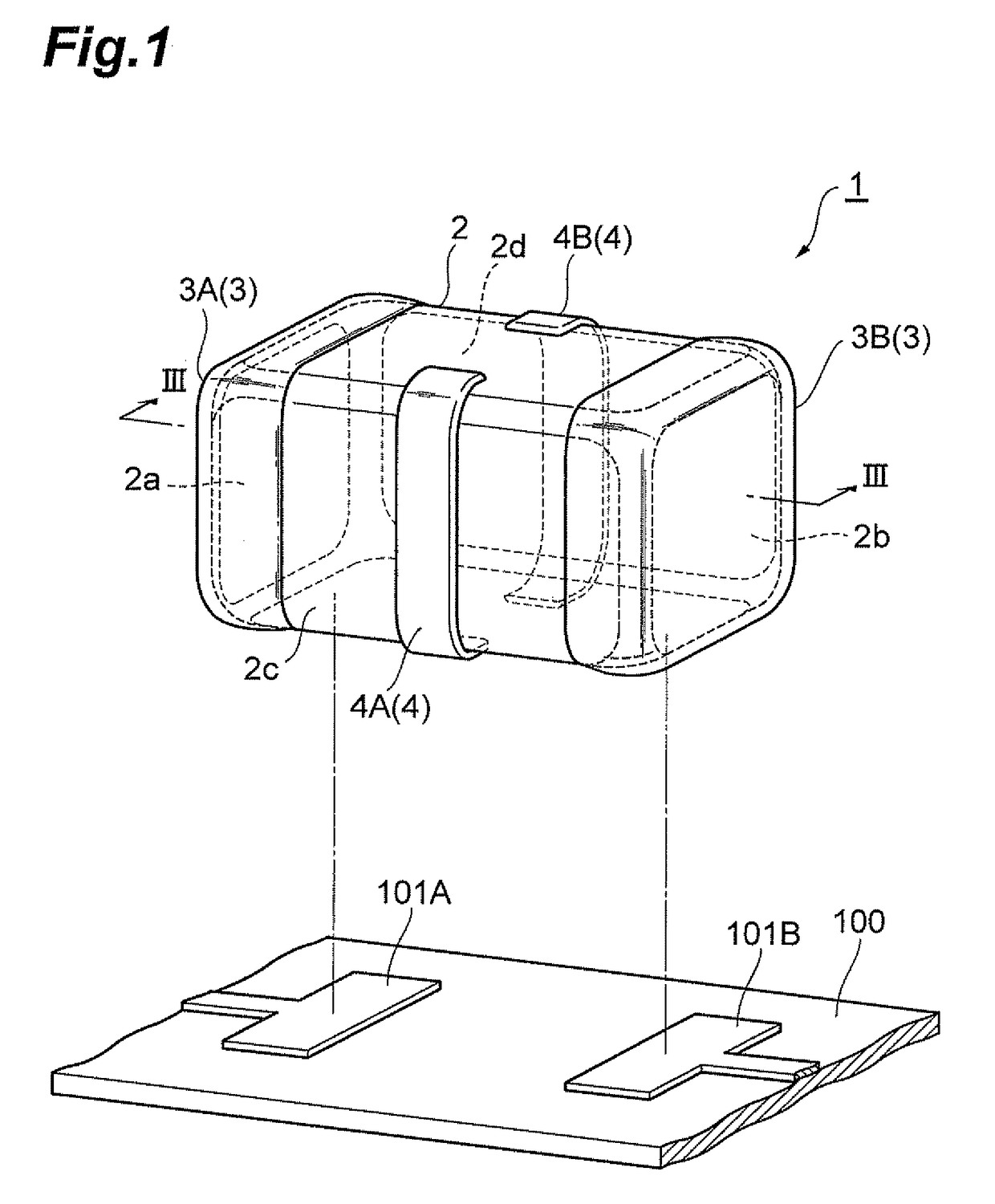
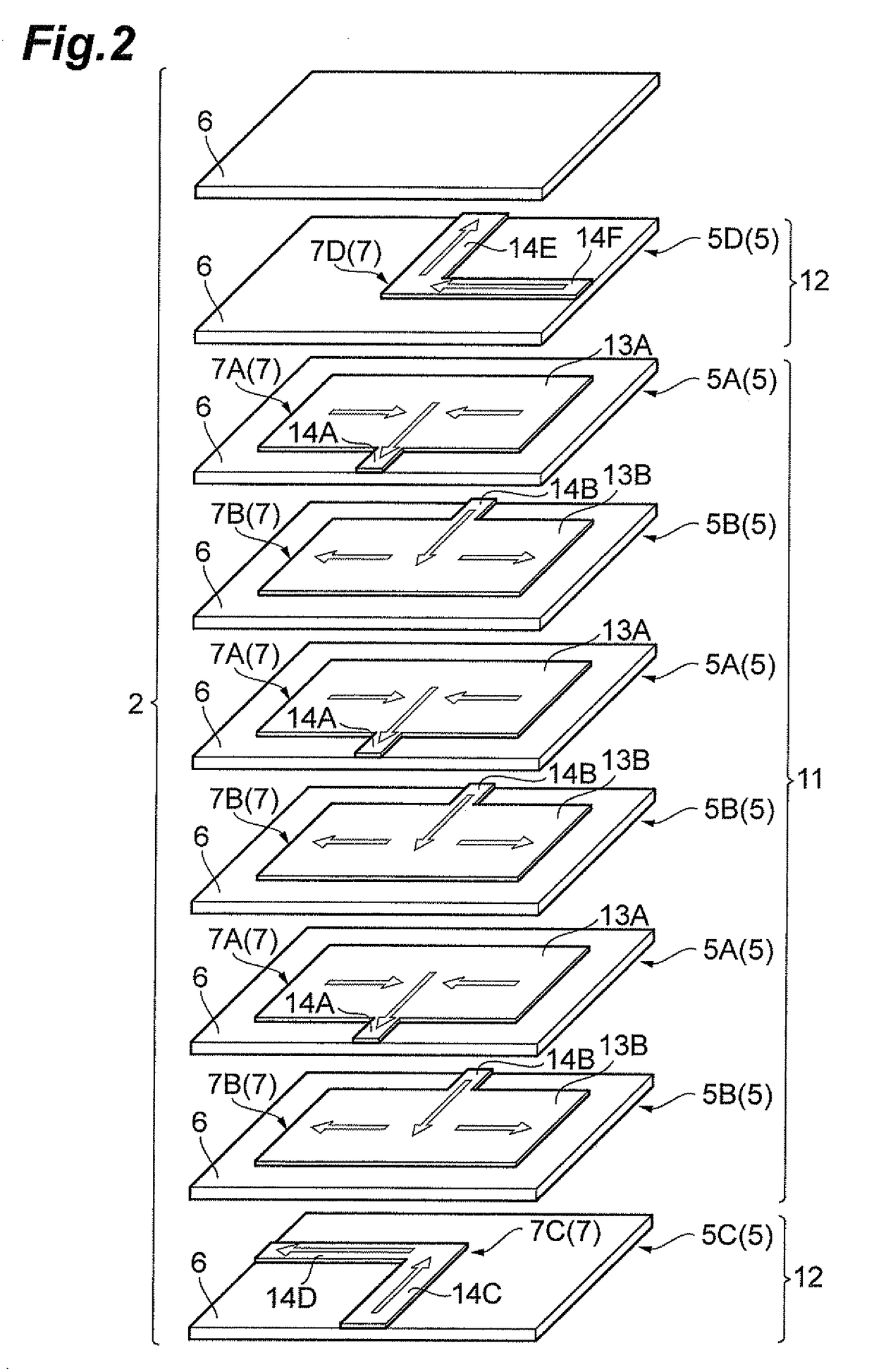
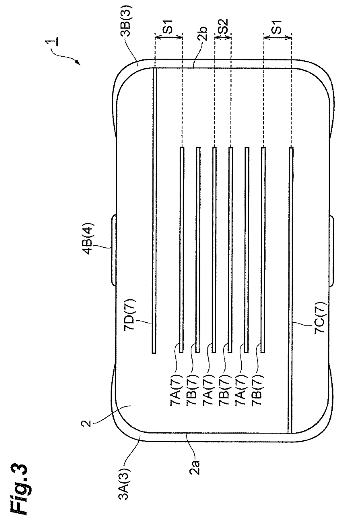
[0026]FIG. 1 is a perspective view showing an embodiment of the mounted structure of the multilayer capacitor according to the present invention. FIG. 2 is a drawing showing a layer structure of the multilayer capacitor shown in FIG. 1, and FIG. 3 is a sectional view along line III-III in FIG. 1.

[0027]As shown in FIGS. 1 to 3, the multilayer capacitor 1 has a laminate 2 of a nearly rectangular parallelepiped shape, external electrodes 3 (3A, 3B) formed on end faces of the laminate 2, and terminal conductors 4 (4A, 4B) formed on side faces of the laminate 2.

[0028]The laminate 2, as shown in FIG. 2, is formed with a plurality of complex layers 5 in each of which an internal electrode 7 is formed in a different pattern on a dielectric layer 6, and dielectric layers 6 laid on ...


PUM


Abstract

In a multilayer capacitor, widths of lead conductors of internal electrode and widths of lead conductors of internal electrode in an ESR control section are smaller than any one of widths of internal electrode and widths of internal electrode in a capacitance section. This narrows cross sections of the conductor portions connecting between the internal electrodes and the external electrodes, so as to her increase ESR. The widths of the respective lead conductors in the ESR control section are wider than widths of respective lead conductors in the capacitance section. This effectively prevents open failure and improves a yield of products.

Description

BACKGROUND OF THE INVENTION[0001]1. Field of the Invention[0002]The present invention relates to a multilayer capacitor and a mounted structure of the multilayer capacitor.[0003]2. Related Background Art[0004]There is a hitherto-known multilayer capacitor having a laminate in which dielectric layers and internal electrodes are alternately laminated together, and external electrodes and terminal conductors formed on side faces of the laminate and electrically isolated from each other.[0005]As a multilayer capacitor of this type, there is, for example, the multilayer capacitor described in Japanese Patent Application Laid-open No. 2003-168621. This multilayer capacitor has four types of internal electrodes. Each of two types of internal electrodes among them has an electrode portion to form a capacitance, and a lead conductor connected to the electrode portion and to a terminal conductor. Each of the other two types of internal electrodes has a lead conductor connected to a terminal e...

Claims


Application Information

Patent Timeline
Patent Type & Authority Patents(United States)
IPC IPC(8): H01G4/228H01G4/06H01G4/005
CPCH01G4/005H01G4/232H01G4/33H01G4/30
Inventor AOKI, TAKASHI
Owner TDK CORPARATION
Why Eureka
Try Eureka