
Solid electrolytic capacitor and its manufacturing method

a technology of solid electrolytic capacitors and manufacturing methods, which is applied in the manufacture of electrolytic capacitors, liquid electrolytic capacitors, electrolytic capacitors, etc., can solve the problems of difficult formation of thin portions of conductive polymer layers, and difficult to form fine conductive polymer layers, etc., to achieve less likely to cause failures and high reliability

Active Publication Date: 2013-12-24
TOKIN CORP
View PDF6 Cites 2 Cited by
  • Summary
  • Abstract
  • Description
  • Claims
  • Application Information

AI Technical Summary

Benefits of technology

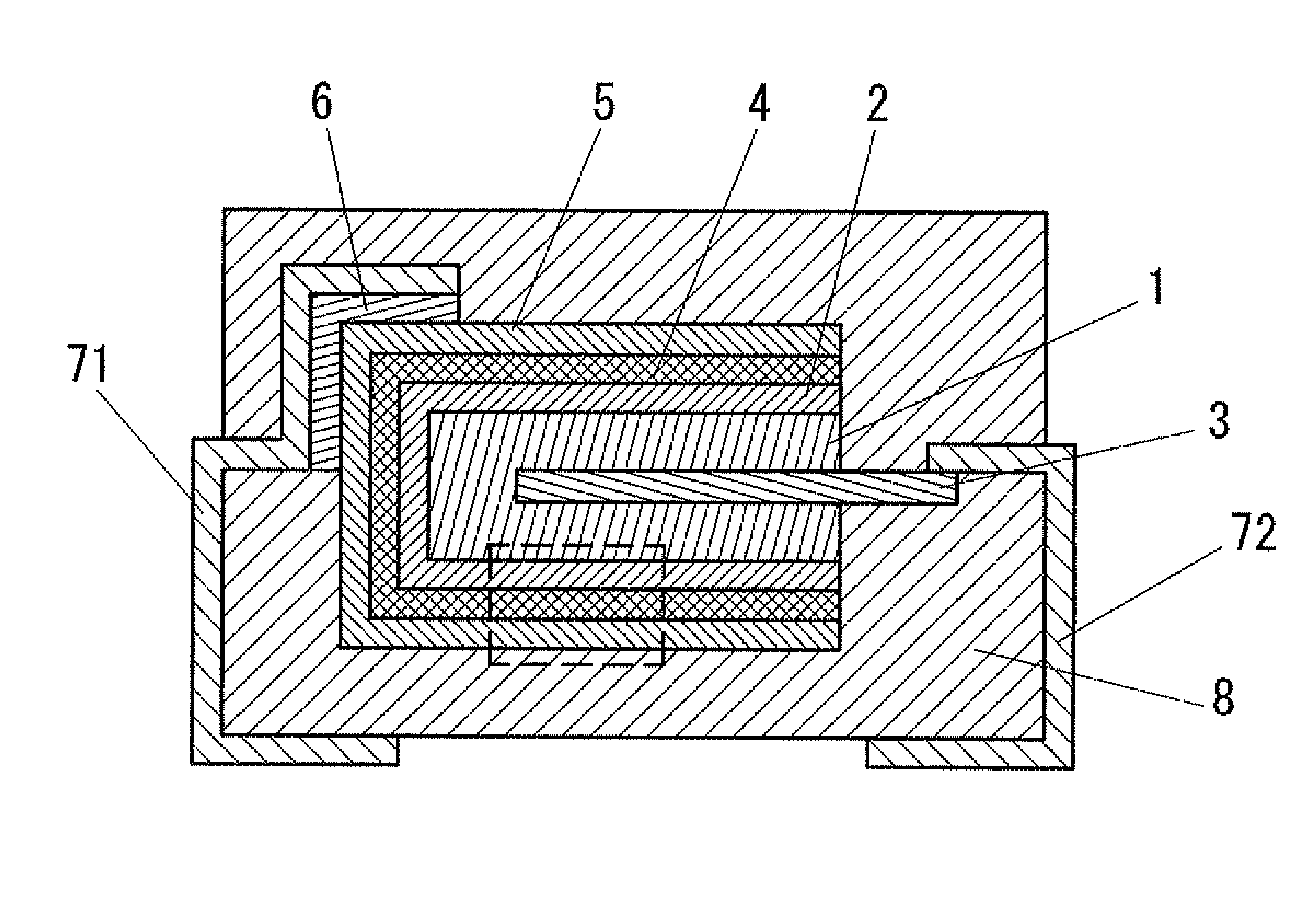
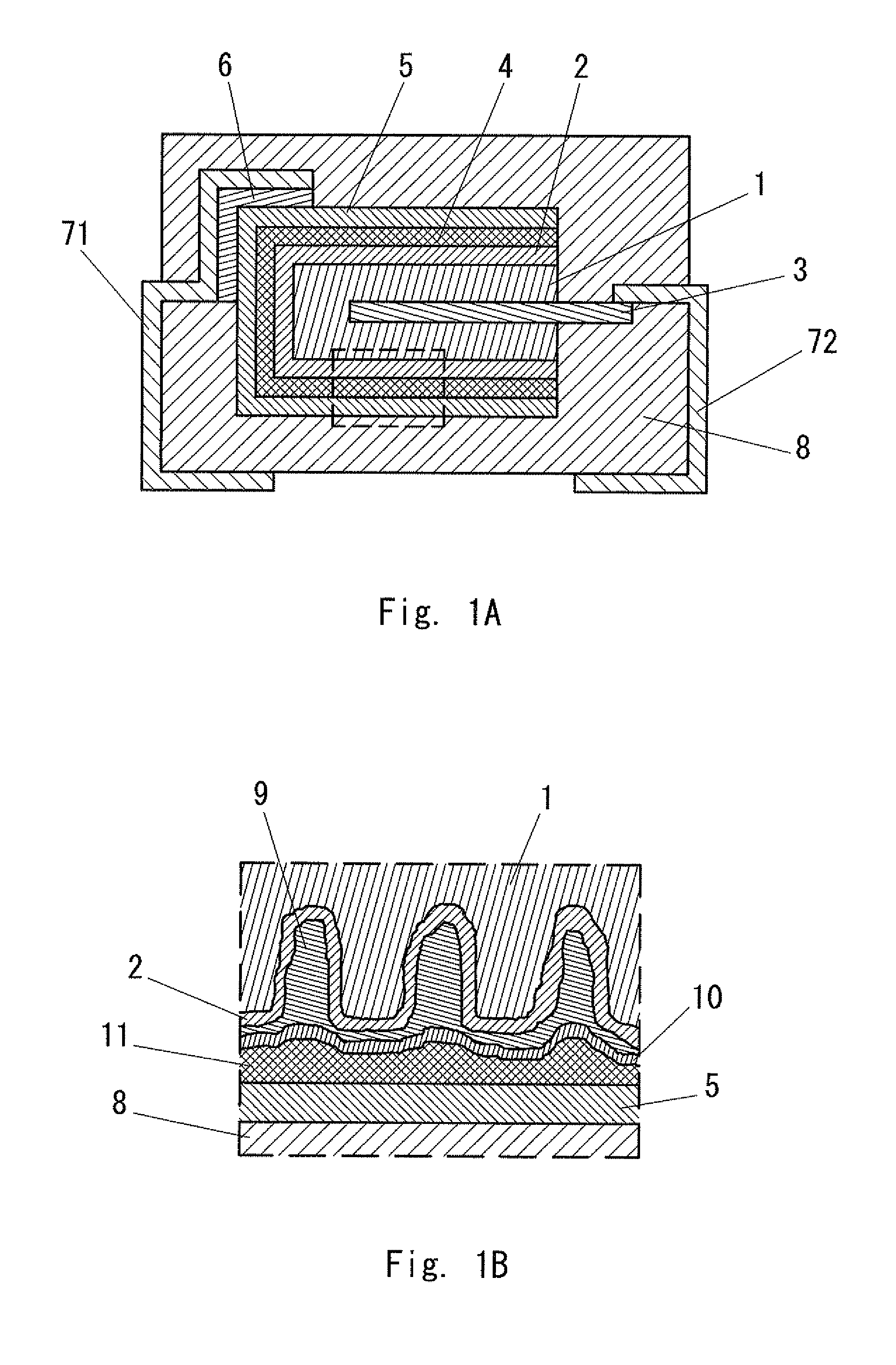
The present invention provides a solid electrolytic capacitor with high reliability that is less likely to fail under heat and stress during packaging and mounting. The capacity of the capacitor is achieved through a process where a dielectric layer and a first solid electrolyte layer are formed on a porous valve metal body, followed by the formation of an amine compound layer and a second solid electrolyte layer. The amine compound layer and conductive polymer layer are electro-statically attracted to each other, resulting in a solid electrolyte layer with uniform thickness and excellent adhesive properties. The resulting capacitor has high tolerance to heat and stresses and is highly reliable.

Problems solved by technology

Therefore, because of the nature of the chemical oxidation polymerization, it is very difficult to form a fine conductive polymer layer having an excellent adhesive property.
However, due to the effects of the surface tension and the wettability of the conductive polymer solution, the central portion of the conductive polymer layer tends to become thicker while the peripheral portion (corner portion) tends to become thinner.
Further, since the adhesive property between the layer formed by the chemical oxidation polymerization and the layer formed by applying and drying the conductive polymer solution is poor, there is a problem that they tend to be separated from each other due to a thermal stress or a mechanical stress that is caused at the time of mounting or the like.

Method used


Image

  • Solid electrolytic capacitor and its manufacturing method
  • Solid electrolytic capacitor and its manufacturing method

Examples


example 1

[0048]A rectangular parallelepiped press body of 3.5 mm in height, 3.0 mm in width, and 1.5 mm in thickness formed of about 30,000 (μFV / g:CV / g) of tantalum powder in which a tantalum wire of 0.4 mm in diameter is embedded as the anode lead 3 was sintered at about 1,500° C. to produce a tantalum sintered body. A voltage of 30 V was applied to this sintered body in a phosphoric acid aqueous solution to carry out anodic oxidation and thereby to form a dielectric layer 2.

[0049]Next, the tantalum sintered body coated by the dielectric layer 2 was submerged in an aqueous solution containing ammonium peroxydisulfate, which is an oxidizing agent, and 1,3,6-naphthalene trisulfonic acid. Next, after dried at a room temperature, it was submerged in 3,4-ethylene dioxythiophene and then kept at a room temperature to polymerize 3,4-ethylene dioxythiophene. A series of these polymerization processes was repeated three times to form a first solid electrolyte layer 9 composed of conductive poly-3,4-...

example 2

[0053]A mixture aqueous solution containing poly-3,4-ethylene dioxythiophene and polystyrene sulfonate in an amount of 3 wt. % (conductive polymer solution A) was used for the formation of the first solid electrolyte layer 9.

[0054]A tantalum sintered body on which a dielectric layer 2 was formed in advance was submerged in the conductive polymer solution A, and then dried at 125° C. for 20 minutes to form a conductive polymer layer. These processes were repeated three times to form a first solid electrolyte layer 9. A commercially-available conductive polymer solution whose D90 is about 30 to 50 nm was used as the conductive polymer solution A. The processes other than these processes for formation of the first solid electrolyte layer 9 were the same as those of Example 1. Further, at this point, the coating rate of the first solid electrolyte layer was 87%.


PUM

PropertyMeasurementUnit
thicknessaaaaaaaaaa
thicknessaaaaaaaaaa
particle diameteraaaaaaaaaa

Abstract

A solid electrolytic capacitor according to an aspect of the present invention includes an anode conductor including a porous valve metal body, a dielectric layer formed on a surface of the anode conductor, and a solid electrolyte layer including a conductive polymer layer formed on a surface of the dielectric layer, in which the solid electrolyte layer includes a first solid electrolyte layer formed on a surface of the dielectric layer, and a second solid electrolyte layer formed on a surface of the first solid electrolyte layer, and at least one continuous or discontinuous layer containing an amine compound exists between the first and second solid electrolyte layers, and inside the second solid electrolyte layer.

Description

INCORPORATION BY REFERENCE[0001]This application is based upon and claims the benefit of priority from Japanese patent application No. 2010-183556, filed on Aug. 19, 2010, the disclosure of which is incorporated herein in its entirety by reference.BACKGROUND OF THE INVENTION[0002]1. Field of the Invention[0003]The present invention relates to a solid electrolytic capacitor and its manufacturing method, in particular to a solid electrolytic capacitor having a low ESR and high reliability, and its manufacturing method.[0004]2. Description of Related Art[0005]The development of a solid electrolytic capacitor in which a dielectric oxide film is formed on a porous body made of a valve metal such as tantalum and aluminum by an anodic oxidation method, and then at least one conductive polymer layer is formed on this oxide film and used as a solid electrolyte layer has been in progress.[0006]The formation method of the conductive polymer layer, which is used as the solid electrolyte layer o...

Claims


Application Information

Patent Timeline
Patent Type & Authority Patents(United States)
IPC IPC(8): H01G9/00
CPCH01G9/025H01G9/028H01G9/15H01G9/0036
Inventor TAKAHASHI, MASANORIIWAI, SATOSHIISHIJIMA, MASAMI
Owner TOKIN CORP
Learn More