Capacitor and method of manufacturing capacitor

a capacitor and manufacturing method technology, applied in the manufacture of electrolytic capacitors, liquid electrolytic capacitors, electrolytic capacitors, etc., can solve the problems of increasing the viscosity of the electrolyte capacitor, reducing the impregnation performance of the electrolyte solution to the capacitor element, and reducing the efficiency of the electrolyte solution impregnation, so as to improve the productivity suppress the increase of the electrolytic capacitor

US10096430B2Active Publication Date: 2018-10-09NIPPON CHIMI CON CORP
23 Cites 2 Cited by

Patent Information

Authority / Receiving Office
US · United States
Patent Type
Patents(United States)
Current Assignee / Owner
Publication Date
2018-10-09

Smart Images

  • Figure 1
    Figure 1
  • Figure 2
    Figure 2
  • Figure 3
    Figure 3
Patent Text Reader

Abstract

A capacitor structure and a manufacturing method achieve suppression of ESR increase and improved productivity for electrolytic capacitors produced by a manufacturing process in which an additive layer is applied to a separator before impregnation of a capacitor element. An anode foil and a cathode foil having undergone an area increasing process are laminated and wound via separators, on which additive layers are formed on respective one surfaces, to produce the capacitor element. At least the separator having a surface at the center side of the capacitor element facing the anode foil and a surface at the outer circumference side of the capacitor element facing the cathode foil, has the additive layer formed on the surface at the center side of the capacitor element.
Need to check novelty before this filing date? Find Prior Art

Description

TECHNICAL FIELD

[0001] The present disclosure relates to a capacitor and a method of manufacturing the capacitor.BACKGROUND ART

[0002] Electrolytic capacitors are passive elements that charge and discharge electrical charges by electrostatic capacity. Such electrolytic capacitors include a capacitor element impregnated with an electrolyte solution and placed in an outer casing, the outer casing is sealed by a seal body, and lead terminals are drawn out from the seal body. The capacitor element includes an anode foil formed of a valve metal foil such as aluminum with an oxide film as a dielectric layer formed thereof, a cathode foil formed of the same or different metal foil and facing the anode foil, and a separator between the anode foil and the cathode foil.

[0003] The anode foil is produced by performing an area increasing process on a valve metal in order to increase the surface area, and then performing a chemical conversion process of applying a voltage in a chemical conversion solu...

Examples

example

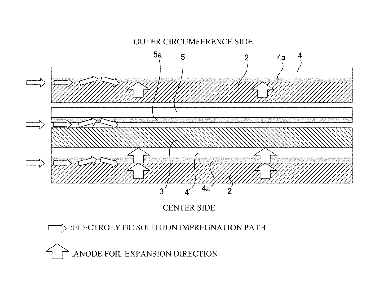
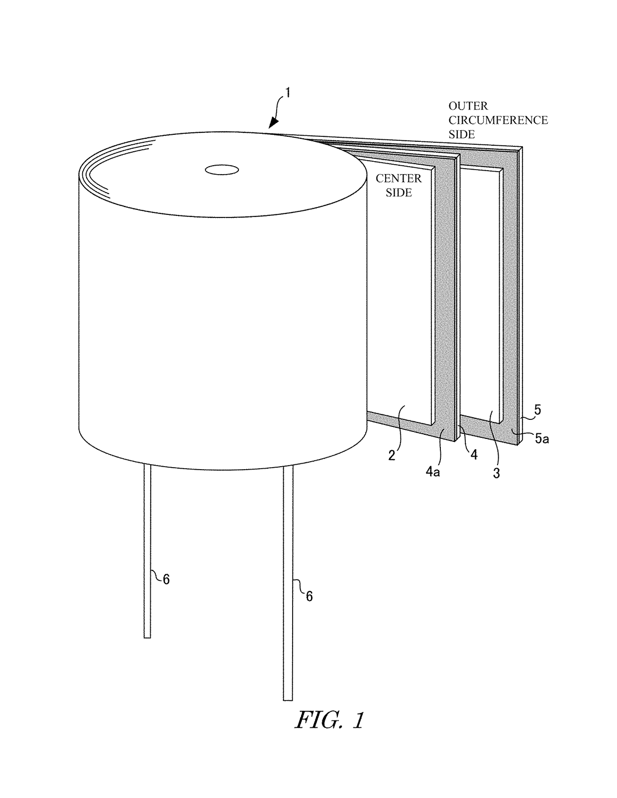
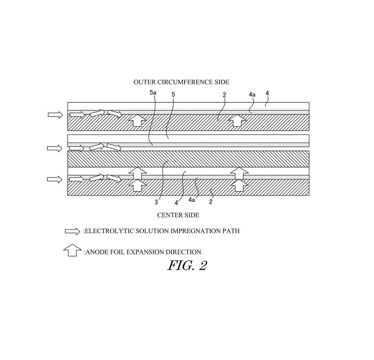
[0061]Examples according to the present disclosure will be explained in detail with reference to FIGS. 1 and 2. The anode foil 2 and the cathode foil 3 were laminated with each other via the separators 4, 5 having respective one surfaces adhered with polyvinyl-alcohol, and wound to produce the capacitor element 1. This capacitor element was impregnated with the electrolyte solution, placed in the outer casing, and this outer casing was sealed by a seal body. A chemical re-conversion process was applied, and the electrolytic capacitor was manufactured. As for the size of the capacitor, the diameter was 13.5 mm, and the entire length was 40 mm.

[0062]The capacitor element 1 according to this example has polyvinyl-alcohol layers 4a, 5a disposed on the respective surfaces of the separators 4, 5 at the center side of the capacitor element 1. That is, the separator 4, which is located adjacent to the anode foil 2 at the surface at the center side of the capacitor element 1 and is located a...