Solid electrolytic capacitor and method for manufacturing the same

Active Publication Date: 2007-07-26
SANYO ELECTRIC CO LTD +1
View PDF5 Cites 1 Cited by
  • Summary
  • Abstract
  • Description
  • Claims
  • Application Information

AI Technical Summary

Benefits of technology

[0022]1. A protruding portion (4) of an anode lead frame (3) is formed by bending a portion of the anode lead frame (3) into a first horizontal portion (41), a linking portion (specifically, sloping portion (42) in FIG. 2), a second horizontal portion (40), and an auxiliary bent portion (43). When forming the protruding portion (4) of the anode lead frame (3), the bending load acting on both sides of the protruding portion (4) is symmetrical and balanced, because processing is preformed using a center impeller structure for pressing symmetrically with both ends of the protruding portion (4) held down. Any displacement due to springback of the anode lead frame (3) is thereby symmetrical, allowing the protruding portion (4) to be kept horizontal. Also, since the pressing load of the welding electrode is supported on both sides of the protruding portion (4) when welding the anode lead (20) to the second horizontal portion (40), the parallelism of the anode lead (20) and the second horizontal portion (40) is not disturbed during welding.
[0025]3. Also, because the contact surface (46) of the second horizontal portion (40) with the anode lead (20) undergoes a pressing

Problems solved by technology

This results in problems such as weak bonding streng

Method used


Image

  • Solid electrolytic capacitor and method for manufacturing the same
  • Solid electrolytic capacitor and method for manufacturing the same
  • Solid electrolytic capacitor and method for manufacturing the same

Examples


Embodiment Construction

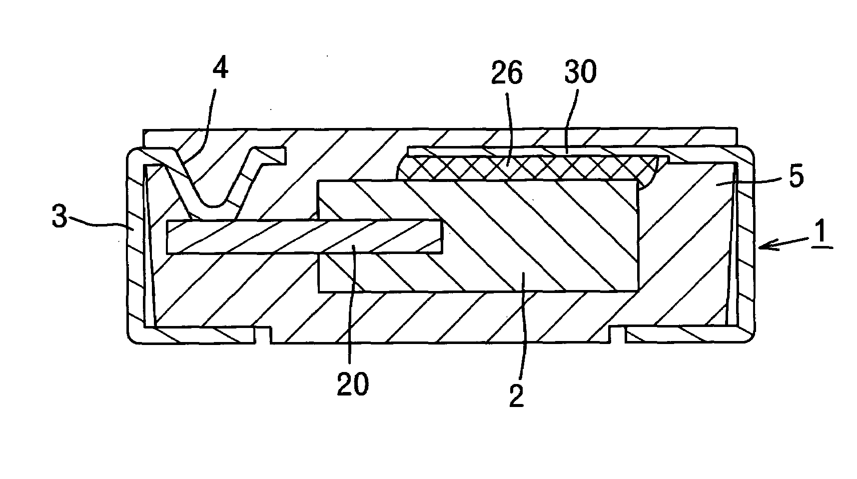
[0040]An embodiment of the present invention will be described below with reference to the accompanying drawings. A capacitor element (2) used in a solid electrolytic capacitor (1) of the present embodiment is the same as the prior art shown in FIG. 10. Here, polypyrrole is used to form the solid electrolytic layer (22) of the capacitor element (2), although other materials that may be used instead include conductive polymers such as polythiophene, polyaniline and polyfuran, and TCNQ (7, 7, 8, 8-tetracyanoquinodimethane) complex. An alloy that includes copper, an iron-nickel alloy or the like is used to form the lead frames (3) and (30).

[0041]Apart from tantalum, the valve metal constituting the anode body (24) and the anode lead (20) may, for example, be niobium, titanium, or aluminum.

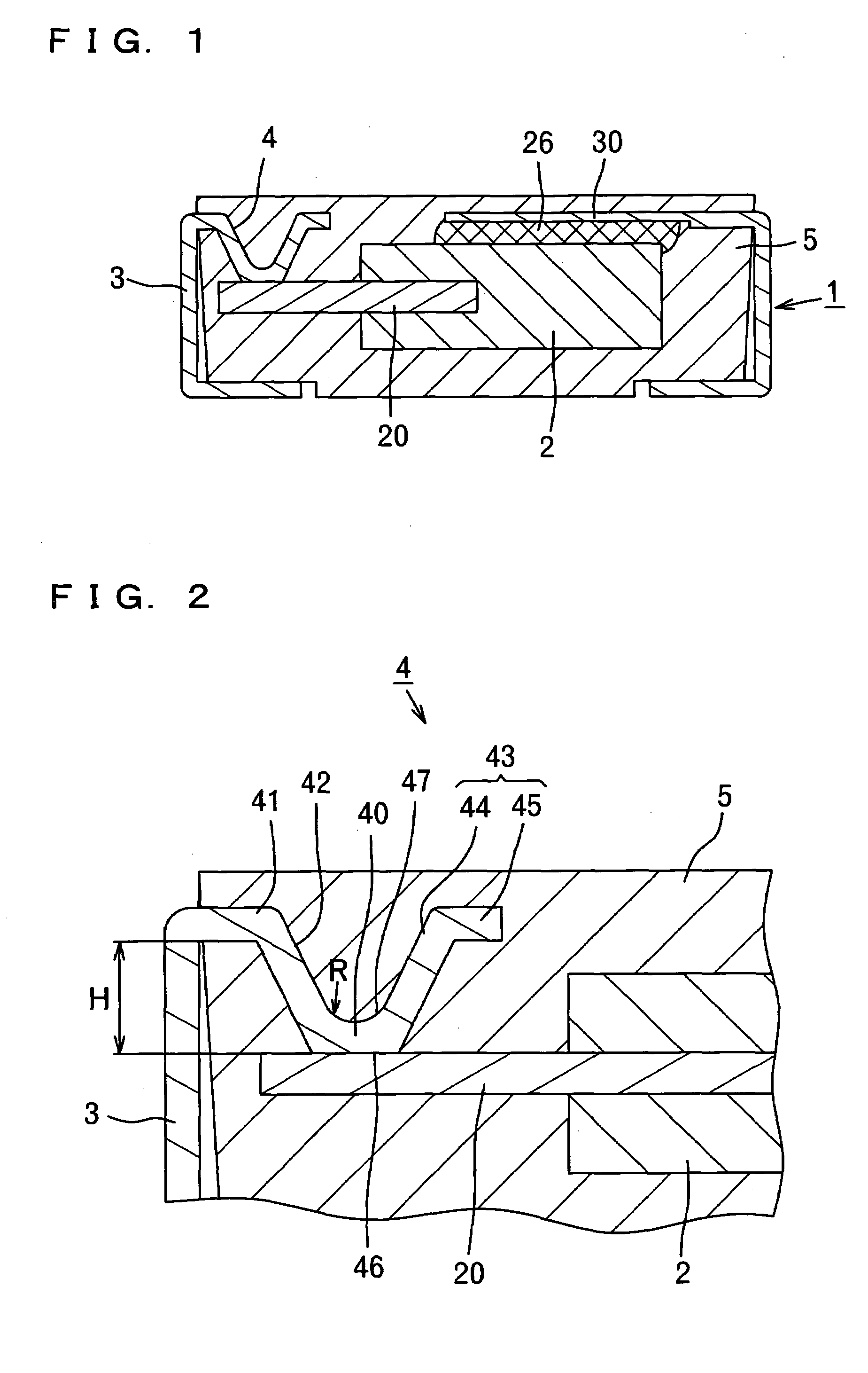
[0042]FIG. 1 is a front sectional view of the solid electrolytic capacitor (1) of the present embodiment. A thin wire-like anode lead (20) protrudes from the capacitor element (2). An anode lead frame...


PUM

PropertyMeasurementUnit
Heightaaaaaaaaaa

Abstract

A portion of an anode lead frame 3 of a solid electrolytic capacitor 1 is bent to form a protruding portion 4 that protrudes toward an anode lead 20. The protruding portion 4 includes a first horizontal portion 41 positioned higher than and substantially parallel to the anode lead 20, a second horizontal portion 40 contacting the anode lead 20, a sloping portion 42 linking the inner end of the first horizontal portion 41 with the outer end of the second horizontal portion 40, and an auxiliary bent portion 43 bent upward from the inner end of the second horizontal portion 40 and substantially symmetrical with the sloping portion 42. A contact surface 46 of the second horizontal portion 40 with the anode lead 20 is formed flat, and a surface 47 of the second horizontal portion 40 on the opposite side to the contact surface 46 is formed with a rounded curvature.

Description

BACKGROUND OF THE INVENTION[0001]1. Field of the Invention[0002]The present invention relates to a solid electrolytic capacitor that includes a lead frame, and a method for manufacturing the same.[0003]2. Description of the Related Art[0004]Conventionally, a solid electrolytic capacitor (1) having the configuration shown in FIG. 8 is known (see Japanese Patent No. 3157722). The solid electrolytic capacitor (1) includes a capacitor element (2) with a thin wire-like anode lead (20) protruding therefrom. An anode lead frame (3) is resistance welded to the anode lead (20), and a cathode lead frame (30) is attached to the peripheral surface of the capacitor element (2) by a conductive adhesive (26). The capacitor element (2) and base ends of both lead frames (3) and (30) are covered with a synthetic resin housing (5), while portions of the lead frames (3) and (30) that protrude outside the housing (5) are bent downward along the peripheral surface of the housing (5), and then horizontall...

Claims


Application Information

Patent Timeline
IPC IPC(8): H01G9/00H01G4/228
CPCH01G9/012Y10T29/417H01G9/10H01G9/042
Inventor MATSUOKA, KEIKOKATO, KAZUHIROSHIBATA, KUNIOFUSHIMI, YOSHIYUKI
Owner SANYO ELECTRIC CO LTD
Why Eureka
Try Eureka