Touch panel structure, touch and display panel structure, and integrated touch display panel structure having antenna pattern and method of forming touch panel having antenna pattern

a touch panel and antenna pattern technology, applied in the direction of antenna details, instruments, antennas, etc., can solve the problems of interference of the antenna operation, easy interference, radiated electromagnetic waves, etc., and achieve the effect of less area and enhanced antenna working rang

Active Publication Date: 2014-02-13
HTC CORP
View PDF5 Cites 207 Cited by
  • Summary
  • Abstract
  • Description
  • Claims
  • Application Information

AI Technical Summary

Benefits of technology

[0012]The touch panel structure, touch and display panel structure, or the integrated touch display panel structure and the method of forming the same disposes the first section set of the carrier on the top surface of the touch module or the display module and disposes the second section set of the carrier on the side surfaces of the housing. In such way, the antenna pattern disposed on the carrier occupies less area from the top surface of the electronic device. The overall size of the top plane of the electronic device may be closer to the viewable area of the display module, while the effective antenna area of the antenna is maintained and the working range of the antenna may be enhanced.

Problems solved by technology

An antenna utilizes electromagnetic waves travelling in the space to transmit or receive messages and is easily interfered by any undesired electromagnetic waves.
Since a mobile phone contains many other electronic components, each inevitably radiating electromagnetic waves during its operation, these radiated electromagnetic waves interfere, more or less, the operation of the antenna.
As a result, some mobile phones have designs that shield these waves radiated from those electronic components, which interferes the operation of the antenna, looking for reducing such unwelcomed interference by the leaking electromagnetic waves.
Generally, such design requires restricting the configuration of the antenna at the housing, the antenna being squeezed either at a single side or at the corner of the housing, and apparently limits the freedom of the layout and design of the antenna, not to mention the ability of the antenna to transmit and receive the signals.
Additionally, it is obvious that not every electronic component of the device is shieldable with a metallic housing or other wave-absorptive or magnetic material.
The touch panel is one of such components, which is required to be touched by a user and is impossible to be fully shielded.
Leak of electromagnetic waves from such components and interference to the antenna can not be prevented.
Still one more problem is that the increasing size of the touch panel leaves little room for the antenna, which worsens all the aforesaid problems.

Method used


Image

  • Touch panel structure, touch and display panel structure, and integrated touch display panel structure having antenna pattern and method of forming touch panel having antenna pattern
  • Touch panel structure, touch and display panel structure, and integrated touch display panel structure having antenna pattern and method of forming touch panel having antenna pattern
  • Touch panel structure, touch and display panel structure, and integrated touch display panel structure having antenna pattern and method of forming touch panel having antenna pattern

Examples


Embodiment Construction

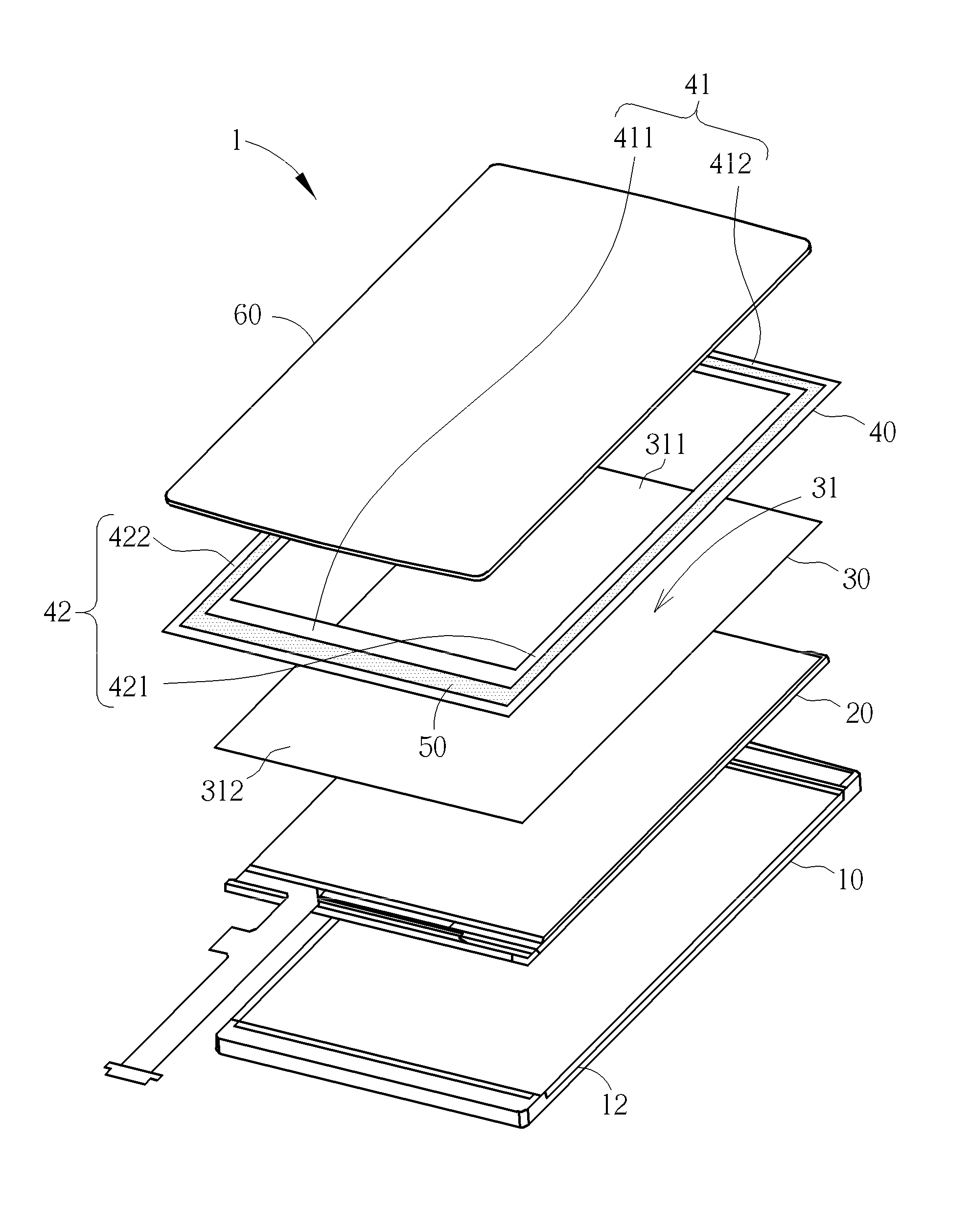
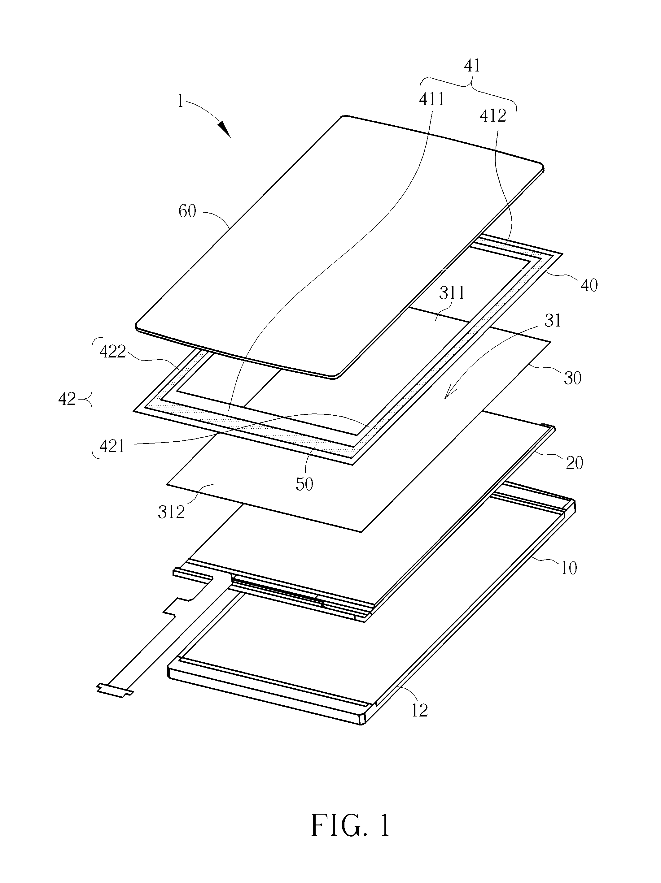
[0021]Please refer to FIG. 1. FIG. 1 is an illustration of one of the embodiments of the invention that shows a touch and display panel structure (or a touch panel structure) having antenna pattern. The touch and display panel structure 1 is used in a portable electronic device or a communication device, which may be, but not limited to, a smart phone, a personal digital assistant (PDA), a tablet computer, etc. The touch and display panel structure 1 includes a housing 10, a display module 20, a touch module 30, a carrier 40, and a cover lens 60. The housing 10 is a housing or part of the housing of the portable electronic device or the communication device. The touch module 30 includes touch sensor unit composed by at least a plurality of touch sensors, an Indium Tin Oxide layer, etc. The display module 20 is disposed in the housing 10, whereas the touch module 30 is disposed on the display module 20. The touch and display panel structure 1 further includes an antenna pattern 50 di...


PUM


Abstract

In a touch panel and display panel structure or an integrated touch display panel structure, an antenna pattern is disposed on a touch module, a display module or an integrated touch display module for an increased distance between the antenna pattern and electronic components below the structure, reducing electromagnetic effect caused by the electronic components and improving the antenna performance. The antenna pattern is arranged at two opposite edges of a top surface of the touch and display module or the integrated touch display module, and also at side surfaces of a housing non-coplanar to the top surface such that the antenna pattern is located outside the displaying area of the display module. Maintaining the effective antenna area and enhancing the working bandwidth of the antenna, the side width of surface of the touch panel and display panel structure or the integrated touch display panel structure is significantly reduced.

Description

BACKGROUND OF THE INVENTION[0001]1. Field of the Invention[0002]The invention relates to a touch panel structure, a touch and display panel structure, and an integrated touch display panel structure having antenna pattern and method of forming the touch panel having such antenna pattern, and more particularly, to such structure that has the antenna pattern disposed away from the back cover of a handheld device and method of forming the touch panel having the antenna pattern.[0003]2. Description of the Prior Art[0004]Antenna is used for transmitting or receiving radio-frequency (RF) signals so that data in the form of radio signals may be conveyed. For electronic products with wireless local area network (WLAN) communication function such as the laptop computers or tablet computers, a built-in antenna is necessary for transmission of data through the wireless network. The advancement of technology in radio communication has led to wireless communication system operating in various di...

Claims


Application Information

Patent Timeline
Patent Type & Authority Applications(United States)
IPC IPC(8): G06F3/041
CPCH01Q1/38H01Q7/00H01Q1/243G06F2203/04103
Inventor YEH, CHIH-SHANKUO, YEN-LIANG
Owner HTC CORP
Why Eureka
Try Eureka