Drainage Device for the Treating Wounds Using a Reduced Pressure

a drainage device and wound technology, applied in wound drains, catheters, bandages, etc., can solve the problems of complicated production, complicated devices, and inability to meet the needs of patients, and achieve the effect of simplifying the design and cost-effectiveness

Active Publication Date: 2008-05-22
BR ENTWICKLUNGS
View PDF26 Cites 218 Cited by
  • Summary
  • Abstract
  • Description
  • Claims
  • Application Information

AI Technical Summary

Benefits of technology

[0009]It is an object of the invention to design a cost-effective device for the vacuum treatment of wounds, the design of which is simplified.
[0016]It is also important that the area of the textile section of the absorption body, enriched with super-absorbent particles, is significantly smaller that that of the envelope, so that the absorption body, without being impeded in its cross section, can approach a circular form. The full utilization of the maximum or almost maximum filling capacity of the absorption body contributes to lowering the costs of treating the wound.
[0023]The envelope of the absorption body many be provided with pulling means, so that the consumed, swollen absorption body can be pulled more easily out of the wound region.
[0025]It is of great advantage that, during the evacuation of the gases, wound secretion particles are not carried along. These remain within the envelope of the absorption body until the whole device is removed from the body of the patient and disposed of or until the swollen absorption body is exchanged. Overall, a device is created for the treatment of wounds using a reduced pressure, for which the wound secretions are aspirated by the nonwoven material of the absorption body, which is interspersed with super absorber, and remain within the envelope surrounding the absorption body without getting back from the envelope into the covered wound space. As the absorption increases, the cross sectional area of the absorption body increases greatly by a multiple and approaches a circular shape. Essentially, no wound secretions are carried along while the reduced pressure is being maintained with the help of a vacuum pump, which can be connected to the device, that is, when evacuating gases. Moreover, it is possible to do without an additional collecting container. If an excess of wound secretion is to be drained off, it is advisable to connect the drainage tube over a check valve to a collecting container, which, in turn, is connected upstream from a vacuum pump with a pressure manometer. In this case, the exchangeable absorption body acts as an intermediate storage device for the secretions emerging from the wound.

Problems solved by technology

The device, so designed, seems complicated and expensive to produce.

Method used


Image

  • Drainage Device for the Treating Wounds Using a Reduced Pressure
  • Drainage Device for the Treating Wounds Using a Reduced Pressure
  • Drainage Device for the Treating Wounds Using a Reduced Pressure

Examples


Embodiment Construction

[0035]The preferred embodiments of the present invention will now be described with reference to FIGS. 1-6 of the drawings. Identical elements in the figures are designated with the same reference numerals.

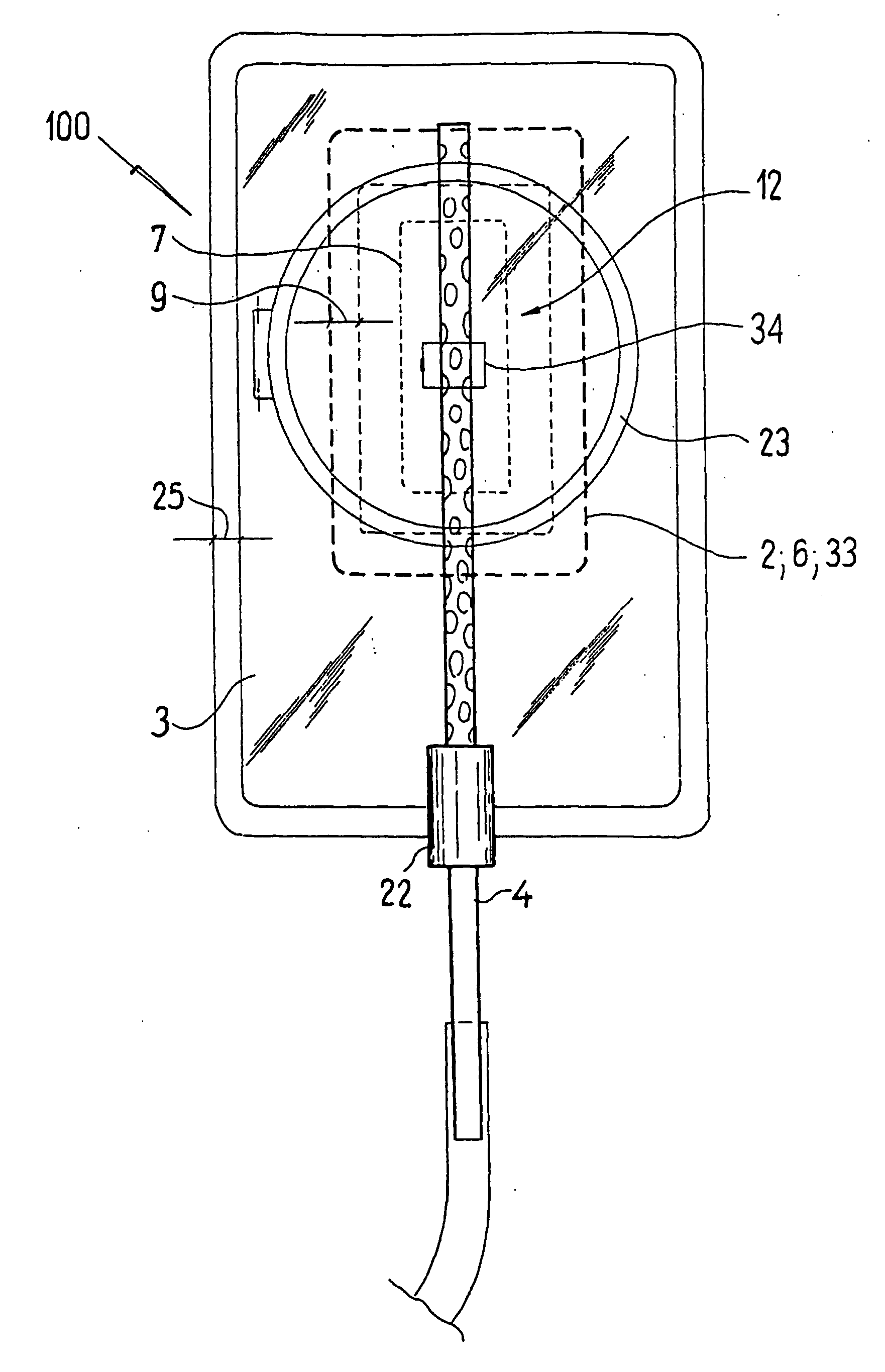
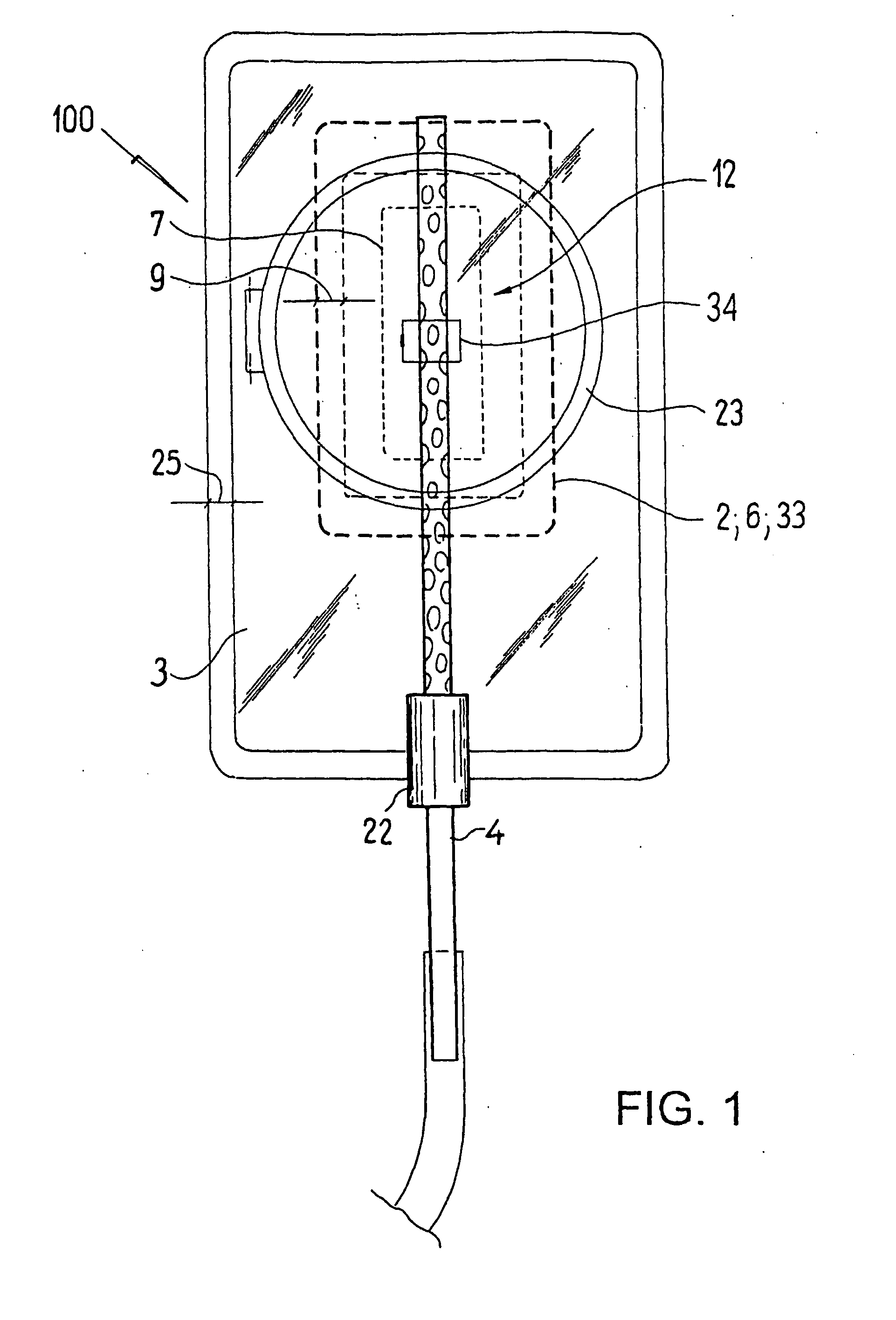
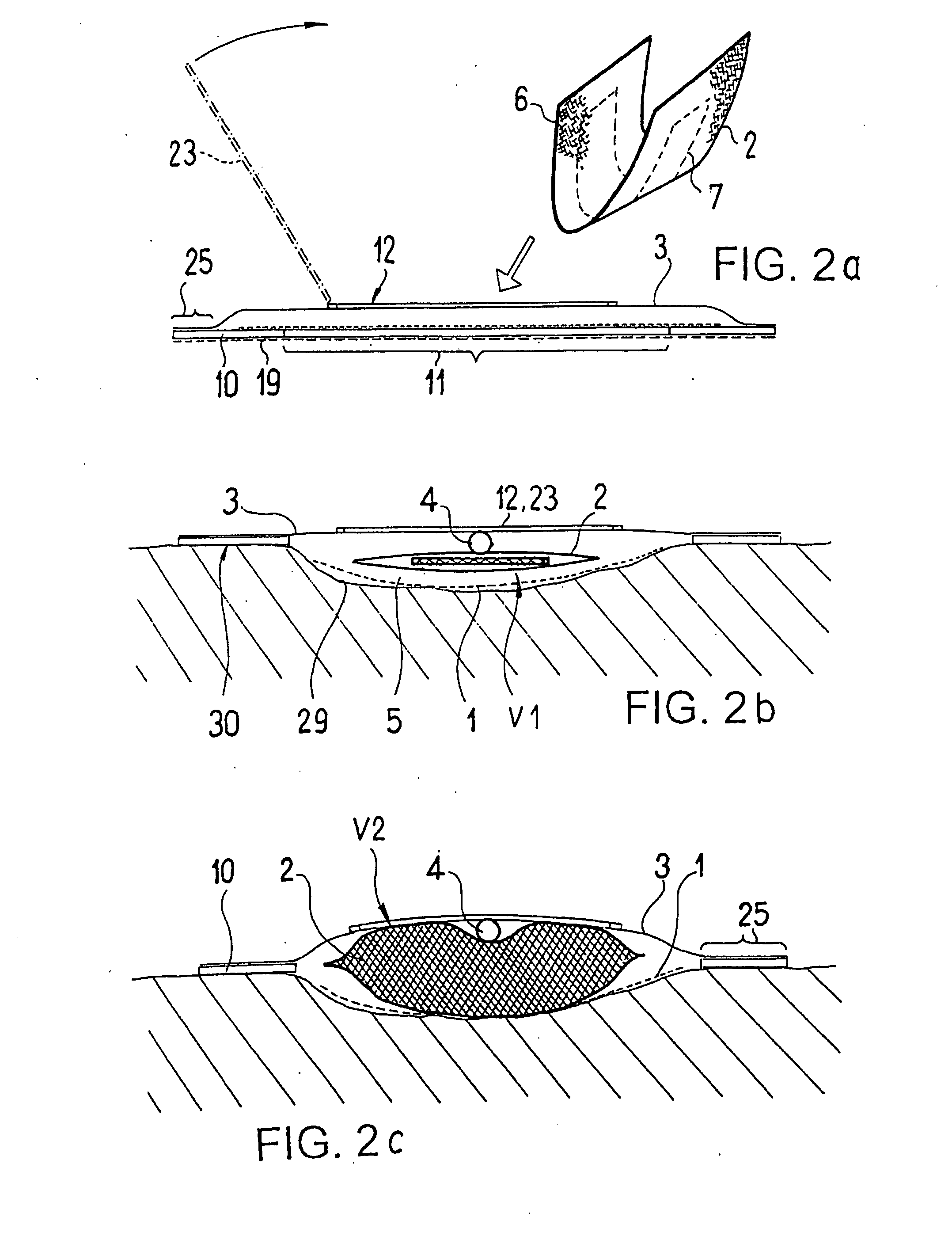
[0036]FIGS. 1 and 2a to 2d show a drainage device 100 for the treatment of wounds using a reduced pressure is shown, comprising a rectangular and a sheet-like, transparent wound-covering 3, a connecting plate 10 of a hydrocolloid-like material, between which there is an absorption body 2, and a drainage tube 4. An opening 11 (compare FIG. 2a), the size of which corresponds to that of the wound, is cut out of the connecting plate 10, so that, when the device 100 is glued to the skin of the patient, a gas-tight wound space 5 results in the region of the wound (compare FIG. 2b). A peripheral edge 25 of the wound-covering element 3 is glued firmly to the connecting plate 10.

[0037]The gas-tight wound space 5 is thus bounded by the wound surface, the wound covering element 3 and the inn...


PUM

PropertyMeasurementUnit
pressureaaaaaaaaaa
pressureaaaaaaaaaa
sizeaaaaaaaaaa

Abstract

The invention relates to a drainage device (100) for the treatment of wounds using reduced pressure, comprising (a) a gas-type wound-covering element (3), which, in the state in contact with the body of the patient, is fastened cohesively at the skin surface around the region of the wound and forms a sealed wound space, remaining between the respective wound and the wound-covering element (3); (b) at least one drainage tube (4), which can be connected to means generating the reduced pressure and can be inserted into the wound space approximately parallel to the wound-covering element (3); and (c) at least one absorption body (2) in the form of at least one layer (7) of a textile section (33), which is interspersed with super-absorbing particles and enclosed in an envelope. Due to the size of the pores of the envelope, the absorbed wound secretions remain within the absorption body (2) and, with that, underneath the wound-covering element (3) until the absorption body is removed from the wound space. An air opening (34) is provided for the wound-covering element (3).

Description

BACKGROUND OF THE INVENTION[0001]The invention relates to a drainage device for treating wounds using a reduced pressure, comprising:[0002]a gas-tight wound-covering element, which consists of a sheet-like material and, when placed in contact with the body of the patient, is fastened adhesively to the surface of the skin about the region of the wound, forming a sealed, wound space remaining between the respective wound and the wound-covering element, and at least one drainage tube, which can be connected to a means, such as a vacuum pump, for producing the reduced pressure and can be inserted prone into the wound space approximately parallel to the wound-covering element and over which the materials in the wound space can be evacuated,[0003]and at least one absorption body, which is disposed in the wound space and absorbs the wound secretions.[0004]A device of the type named above is known from the DE 195 17 699. The known device has a covering sheet for covering the wound flat and ...

Claims


Application Information

Patent Timeline
Patent Type & Authority Applications(United States)
IPC IPC(8): A61M27/00A61F13/02A61M1/00
CPCA61F13/00068A61M27/00A61F2013/00182A61F2013/00255A61F2013/00412A61F2013/00536A61F2013/0054A61F2013/0057A61F2013/00714A61F2013/0074A61F2013/00744A61F2013/00748A61F2013/00846A61F2013/00863A61M1/0031A61M1/0084A61M1/0088A61F2013/00174A61M1/74A61M1/962A61M1/912
Inventor RIESINGER, BIRGIT
Owner BR ENTWICKLUNGS
Why Eureka
Try Eureka