Combined patient interface and exhaust assembly

a patient interface and exhaust assembly technology, applied in respirators, breathing masks, breathing protection, etc., can solve the problems of inability to adjust the flow rate of fluid to the square root of pressure, undesirable re-inhalation of exhaled gas, and inability to purge. the natural relationship of fluid flow rate to pressure may be unacceptable in a ventilation circui

Inactive Publication Date: 2003-07-01
RIC INVESTMENTS LLC
View PDF49 Cites 235 Cited by
  • Summary
  • Abstract
  • Description
  • Claims
  • Application Information

AI Technical Summary

Problems solved by technology

Rebreathing of exhaled gas is undesirable, of course, because the exhalation flow contains CO.sub.2.
This purging becomes a more difficult problem the further the exhalation valve is located from the patient interface, due to the amount of residual exhaled gas in the intervening ventilation circuit dead space.
However, the naturally occurring relationship of fluid flow rate to pressure (flow is proportional to the square root of pressure) may be unacceptable in a ventilation circuit for a number of reasons.
However, an exhalation valve with a flow characteristic that varies naturally with pressure variations in the patient circuit may not be suitable as a patient circuit exhaust valve.
With many conventional exhalation valves, the si

Method used


Image

  • Combined patient interface and exhaust assembly
  • Combined patient interface and exhaust assembly
  • Combined patient interface and exhaust assembly

Examples


Embodiment Construction

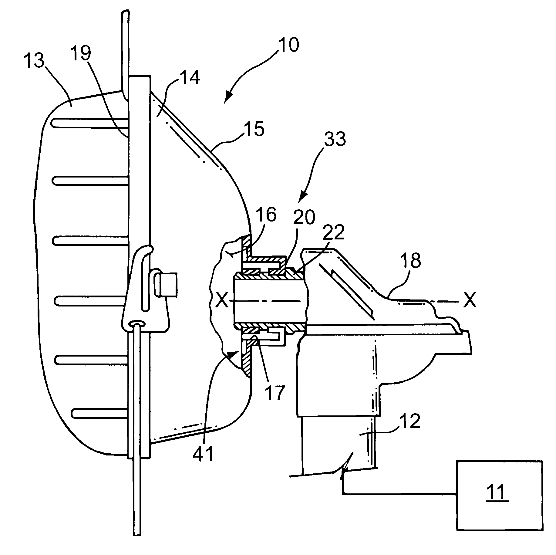
There is generally indicated at 10 in FIG. 1 a patient interface assembly for communicating a flow of breathing gas produced by a pressure generator 11 and carried by a patient circuit 12 to an airway of patient (not shown). As the prior art is replete with descriptions of patient circuits and various types of pressure generators, including CPAP devices, bilevel devices, autotitration devices, ventilators, and even a tank of pressurized gas, no further description of these items is necessary for present purposes. In the illustrated embodiment, patient interface assembly 10 preferably comprises either a full or partial face mask 14 that fits over at least part of the patient's face, including the mouth, the nares, or both for communicating a flow of breathing gas from the gas source to an airway of a patient. In the illustrated embodiment, patient interface assembly 10 includes a faceplate 15 and a seal 13 for contacting the surface of the patient. Faceplate 15, seal 13, or both defi...


PUM


Abstract

A combined patient interface and integrated exhaust assembly that passes a controlled flow of gas from an interior of a patient interface to ambient atmosphere at a predetermined flow rate irrespective of variations of pressure in the interior of the patient interface device relative to ambient atmosphere. Control of the flow of exhaust gas is achieved by varying the effective cross sectional area of the exhaust path communicating the interior of the patient interface with ambient atmosphere based on the pressure in the interior of the patient interface relative to ambient atmospheric pressure.

Description

1. Field of the InventionThe present invention pertains to a combined patient interface and integrated exhaust assembly, and, in particular, to such a combination in which the exhaust assembly provides a controlled flow of exhaust gas, such as a constant flow of gas, from the interior of the patient interface over a range of pressures within the patient interface relative to ambient atmosphere.2. Description of the Related ArtConventional exhaust assembles are used, for example, to provide an exhaust flow path for exhaled air in a ventilation circuit, which supplies a continuous flow of breathing gas to a spontaneously breathing patient. During the exhalation phase of the patient's breathing, exhalation gas backflows in the ventilation circuit and, unless exhausted from the circuit, can be rebreathed by the patient during the next inhalation phase. Rebreathing of exhaled gas is undesirable, of course, because the exhalation flow contains CO.sub.2. Reliable and thorough exhaustion or...

Claims


Application Information

Patent Timeline
IPC IPC(8): A61M16/08A61M16/20A61M16/06
CPCA61M16/06A61M16/08A61M16/20A61M16/0683A61M16/0816A61M16/0825
Inventor SEROWSKI, ANDREW
Owner RIC INVESTMENTS LLC
Why Eureka
Try Eureka