Anti-rolling tank control device

A technology for anti-rolling tanks, control devices, applied in the direction of reducing ship motion through displacement, etc.

Active Publication Date: 2011-12-21
SHANGHAI HUNTER MARINE EQUIP CO LTD
View PDF7 Cites 0 Cited by
  • Summary
  • Abstract
  • Description
  • Claims
  • Application Information

AI Technical Summary

Problems solved by technology

[0005] The main defect of the above-mentioned prior art is that the alternating period of water can only be adjusted to the direction of increasing and the period cannot be reduced, so it is difficult to realize stepless continuous control of

Method used


Image

  • Anti-rolling tank control device
  • Anti-rolling tank control device
  • Anti-rolling tank control device

Examples


Embodiment Construction

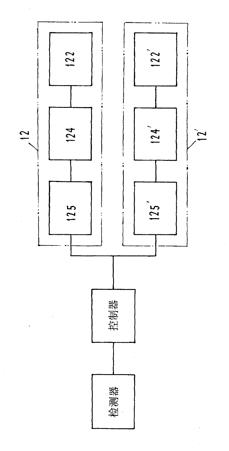
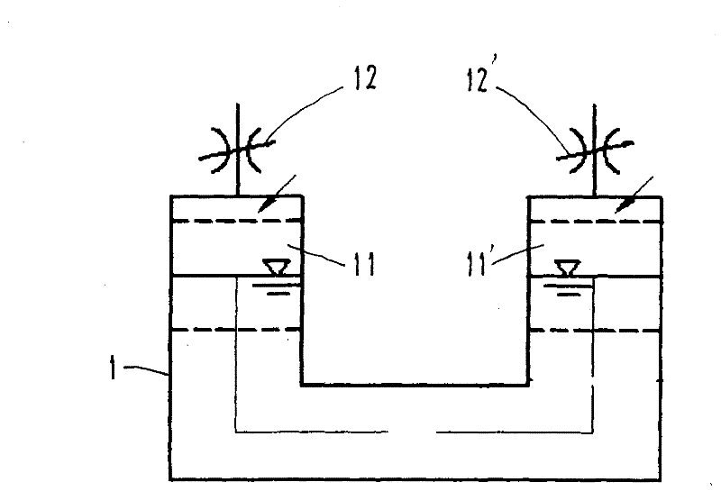
[0020] Reference figure 1 , 2 , Anti-rolling tank control device, including U-shaped anti-rolling tank 1, port side air chamber 11, starboard side air chamber 11', left throttle assembly 12, right throttle assembly 12', detector and controller.

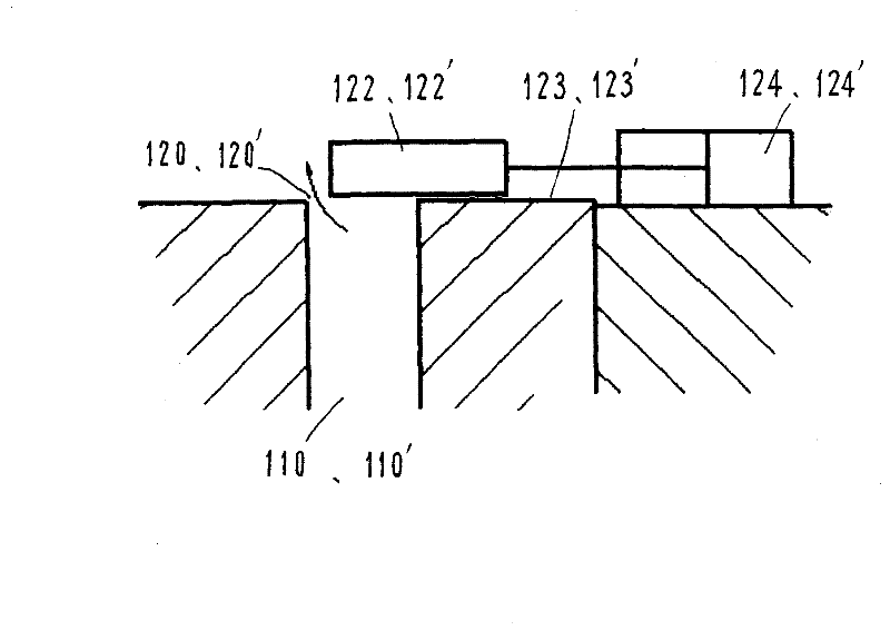
[0021] The U-shaped anti-rolling tank 1 has a structure similar to or the same as that of the prior art. A port side air chamber 11 and a starboard side air chamber 11' are formed on both sides of the U shape, and they are sealed in the left and right air chambers. The tops of 11 and 11' are respectively provided with a left throttle channel 110 and a right throttle channel 110' (e.g. image 3 , 5 ), the top ends of the left and right throttling channels 110, 110’ open to the atmosphere, that is, image 3 , 5 As shown in the left throttle opening 120 and the right throttle opening 120', the left and right throttle passages 110, 110' can be provided with a left throttle assembly 12 and a right throttle assembly 12'.

[0022] The left thrott...


PUM


Abstract

An anti-rolling water tank control device mainly solves technical problems such as improving ship anti-rolling effect. There is a throttling component on the second channel, the second component is connected to a controller, the controller is connected to a detector, the detected ship swing period signal is input to the controller, and the control signal is output to the second throttling component according to the set rules. The flow assembly adjusts the effective cross-sectional area of ​​the second throttling channel to realize the water level alternation period of the U-shaped anti-rolling tank which is the same as the ship's swaying period, and is suitable for various U-shaped anti-rolling tanks.

Description

Technical field: [0001] The invention relates to a device for reducing rolling motion of a ship by transferring liquid, and in particular to a control device for the device. Background technique: [0002] The anti-rolling water tank is one of the devices to reduce the roll of the ship. It has the advantages of lower cost than the fin stabilizer and can play a role at any speed (including zero speed). It is widely used in various types of ships above 500 tons. The anti-rolling principle of the boat and the anti-rolling water tank is based on the theoretical analysis results of Krylov-Blagoveshinski. The main point is that due to the small roll damping coefficient of the water tank, the amplification factor The frequency characteristics of the ship show double peaks, which is equivalent to two main harmonic frequencies. If the wave disturbance frequency is near the two main harmonic frequencies, the function of the uncontrolled passive U-shaped water tank is to increase the ro...

Claims


Application Information

Patent Timeline
Patent Type & Authority Patents(China)
IPC IPC(8): B63B39/03
Inventor 贾正余黄宇徐军韦建新
Owner SHANGHAI HUNTER MARINE EQUIP CO LTD
Why Eureka
Try Eureka