Current transformer

A technology for current transformers and conductive tubes, applied in the field of transformers, can solve the problems of failing to meet the temperature rise requirements, insulation damage, insulation aging and shortening the service life of equipment, reducing volume, increasing effective cross-sectional area, and solving Effects of installation problems

Inactive Publication Date: 2018-02-16
TIANSHUI CHANGKAI MUTUAL INDUCTOR MFR
View PDF7 Cites 2 Cited by
  • Summary
  • Abstract
  • Description
  • Claims
  • Application Information

AI Technical Summary

Problems solved by technology

[0002] In the transformer industry, the primary copper conductor in the high-current transformer will produce a current skin effect after passing through the current, and the charge will concentrate on the surface of the primary conductor. As time goes by, the

Method used


Image

  • Current transformer
  • Current transformer
  • Current transformer

Examples


Example Embodiment

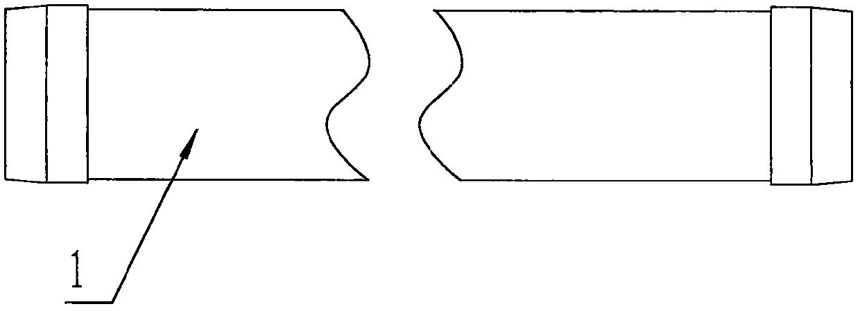
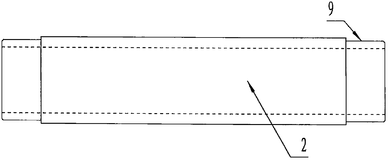
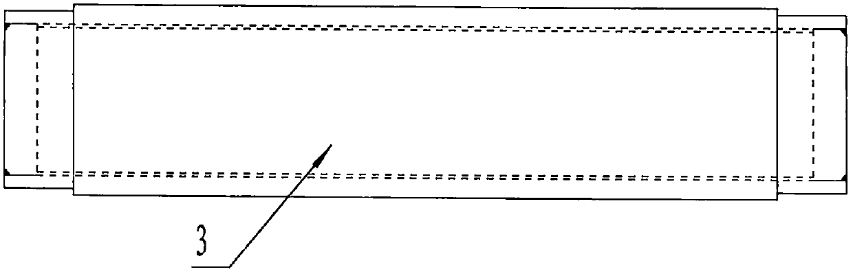
[0009] Such as figure 1 , figure 2 , image 3 As shown, the primary coil 3 has a split structure, which is formed by sleeved cylindrical conductive rod 1 and tubular conductive tube 2 and then welded by silver welding. This split structure allows current to flow through the conductive rod 1 and the conductive tube 2 , Can overcome the impact of skin effect; such as Figure 4 , Figure 5 As shown, the primary wiring board 4 is in the shape of "L" and is composed of a connecting arm 5 and a flat wiring board 6. The flat wiring board 6 has threaded holes 8 and the upper end of the connecting arm 5 is provided with a connecting hole 7 and the conductive tube 2 is provided with steps at both ends 9 is installed in the connecting hole 8 and soldered with silver solder, so that the primary coil 3 and the terminal board 4 are connected together.


PUM


Abstract

The invention discloses a current transformer, which is capable of solving the problem of temperature rise of a primary copper conductor due to a skin effect. The current transformer comprises a primary coil and two primary wiring boards, wherein the primary coil is formed by combining a cylindrical conducting rod and a tubular conducting tube sleeving the cylindrical conducting rod; each wiring board is L-shaped and comprises a connecting arm and a flat wiring board; a connection hole is formed in the upper end of each connecting arm; and the primary coil is connected with the wiring boards through the corresponding connection holes.

Description

technical field [0001] The invention relates to a transformer, in particular to a large current transformer. Background technique [0002] In the transformer industry, the primary copper conductor in the high-current transformer will produce a current skin effect after passing through the current, and the charge will concentrate on the surface of the primary conductor. As time goes by, the temperature of the conductor surface will continue to rise. The aging of the insulation shortens the service life of the equipment, and even leads to insulation damage, which fails to meet the temperature rise requirements stipulated by the national standard. Contents of the invention [0003] The technical problem to be solved by the present invention is to provide a current transformer, which can solve the temperature rise problem of the primary copper conductor due to the skin effect. [0004] In order to solve the above technical problems, the technical solution of the present inven...

Claims


Application Information

Patent Timeline
IPC IPC(8): H01F27/28H01F27/29H01F27/34H01F38/30
CPCH01F27/28H01F27/29H01F27/34H01F38/30
Inventor 张才丽史纪平潘志清
Owner TIANSHUI CHANGKAI MUTUAL INDUCTOR MFR
Why Eureka
Try Eureka