Carburetor

a carburetor and carburetor technology, applied in the field of carburetor, can solve the problems of inability to carry out mid- or high-output operations smoothly, and create temporary fuel flow rate deficiency, and achieve the effects of easy compliance with exhaust gas restrictions, smooth transition, and high outpu

Inactive Publication Date: 2005-02-17
ZAMA JAPAN
View PDF16 Cites 0 Cited by
  • Summary
  • Abstract
  • Description
  • Claims
  • Application Information

AI Technical Summary

Benefits of technology

[0006] The present invention was developed with the aim of solving the above-stated problems in which the transition from low-output operation to mid- or high-output operation cannot be carried out smoothly when the venturi diameter is increased in an attempt to achieve higher output in the above-described conventional carburetors ha...

Problems solved by technology

However, the fuel flow rate restriction and adjustment devices, such as those described above, separately restrict or correct the flow rate of fuel that flows respectively through the main system and the low-speed system.
The disadvantages for the above-described conventional carburetors having such devices are that when the venturi diameter is increased in order to ensure high ...

Method used


Image

  • Carburetor
  • Carburetor
  • Carburetor

Examples


Embodiment Construction

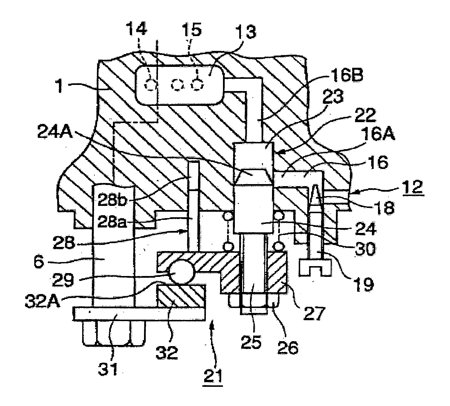
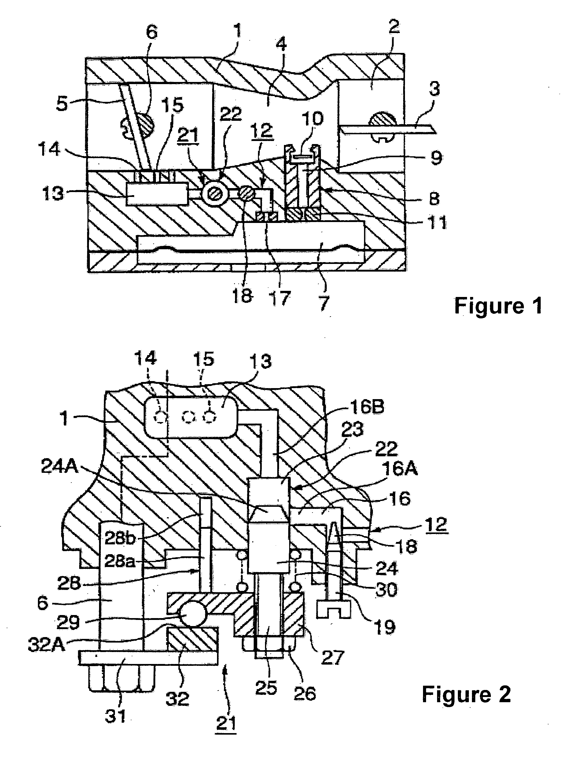
[0017] The embodiments of the present invention are described below with reference to the diagrams. As shown in FIGS. 1 and 2, an air intake channel 2 that is formed completely through the carburetor main body 1 and extends in the lateral direction has, in order from the inlet to the outlet, a choke valve 3, a venturi 4, and a throttle valve 5. A constant fuel chamber 7, which may be a float type or a diaphragm type and which is a diaphragm type in this embodiment, is disposed in the lower portion of the carburetor main body 1.

[0018] A main nozzle 9 doubling as the main fuel channel opens into the narrowest portion of the venturi 4. A check valve 10 that prevents the air in the air intake channel 2 from flowing into the constant fuel chamber 7 is disposed at the outlet of the main nozzle 9. A main jet 11 that restricts the maximum flow rate of the main fuel is disposed in the inlet of the main nozzle 9, facing the constant fuel chamber 7. The main nozzle 9, check valve 10, and main...


PUM

PropertyMeasurementUnit
Speedaaaaaaaaaa

Abstract

A flow rate control mechanism is provided to a low-speed fuel system that is independent from the main fuel system of a carburetor. The mechanism causes the valve element to move in a linear fashion by means of a cam coupled to the throttle stem. The mechanism increases the effective cross-sectional area of the low-speed fuel channel as the throttle valve opens from the idle position to the maximum degree of opening until the point in time at which the main fuel begins to flow, and thereafter causes the low-speed fuel flow rate to decrease and become zero in the high-output region. The transition from low-speed fuel to main fuel is made smooth, ensuring higher output and a stable fuel flow rate in the high-output region.

Description

FIELD OF THE INVENTION [0001] The present invention relates to a carburetor for supplying fuel to an engine, and more particularly to a type of carburetor that has a mechanism for smoothing the transition from low-output operation to mid- and high-speed operation. BACKGROUND OF THE INVENTION [0002] In carburetors for automobile engines having a main system for delivering main fuel to the venturi area of an air intake passage that passes through the carburetor main body, and a low-speed system for delivering low-speed fuel to the throttle valve area, the low-speed system is typically branched from the main system. In contrast, in carburetors for general-purpose engines, see e.g. Japanese Utility Model Application Laid-open No. 47-38218 and Japanese Patent Application Laid-open No. 55-69748, the two systems are separated and the low-speed system is made independent with respect to the main system; the advantages of which are the main fuel begins to flow early, and there is no back ble...

Claims


Application Information

Patent Timeline
IPC IPC(8): F02M17/04F02M19/06
CPCF02M17/04
Inventor NONAKA, TAKUMI
Owner ZAMA JAPAN
Why Eureka
Try Eureka