Door Rail System

a rail system and door technology, applied in the field of doors, can solve the problems of difficult or impossible to remove the rail from the glass panel, lack of the efficiency of combining cut-to-fit modular side covers with a plurality, and difficulty in removing rails from glass panels, etc., to achieve the effect of facilitating and more efficiently accommodating varying doorway widths

Active Publication Date: 2022-01-20
C R LAURENCE
View PDF0 Cites 1 Cited by
  • Summary
  • Abstract
  • Description
  • Claims
  • Application Information

AI Technical Summary

Benefits of technology

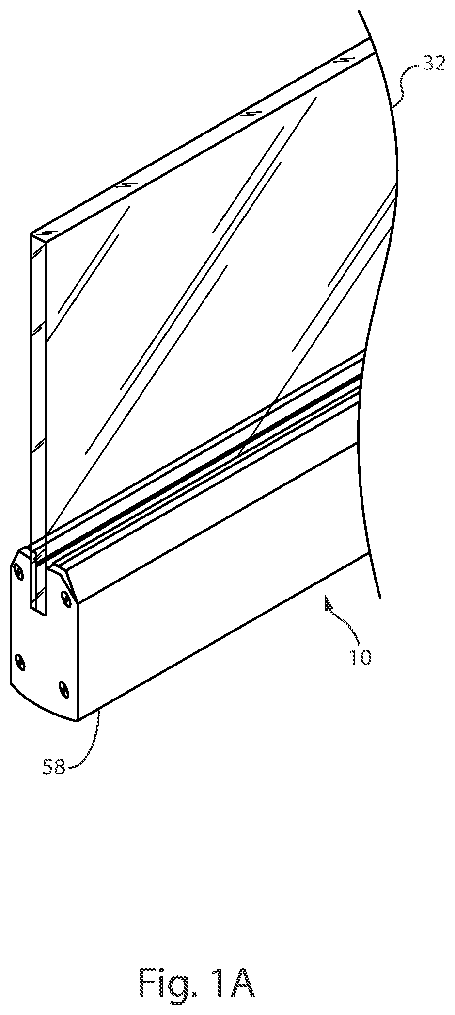
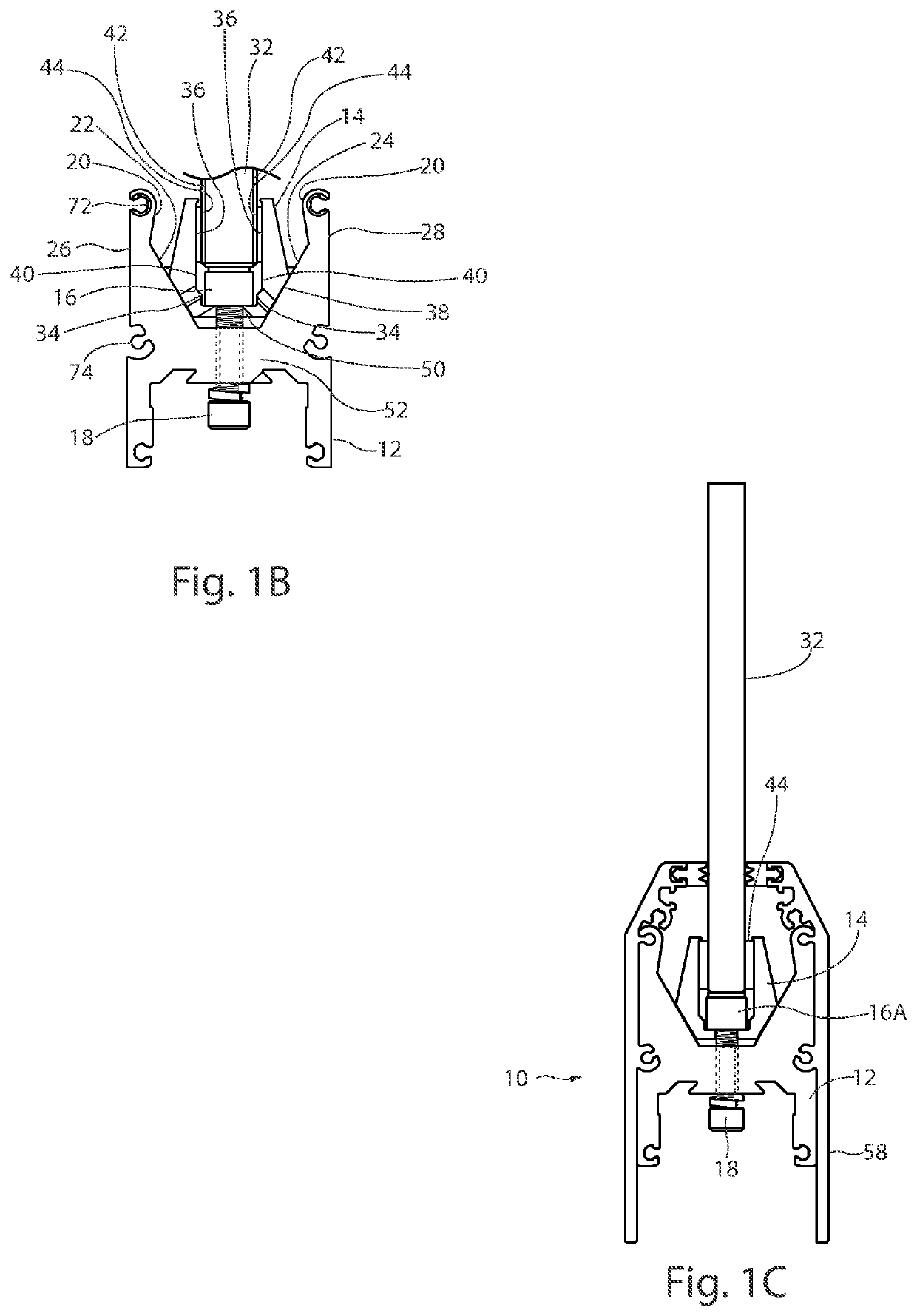
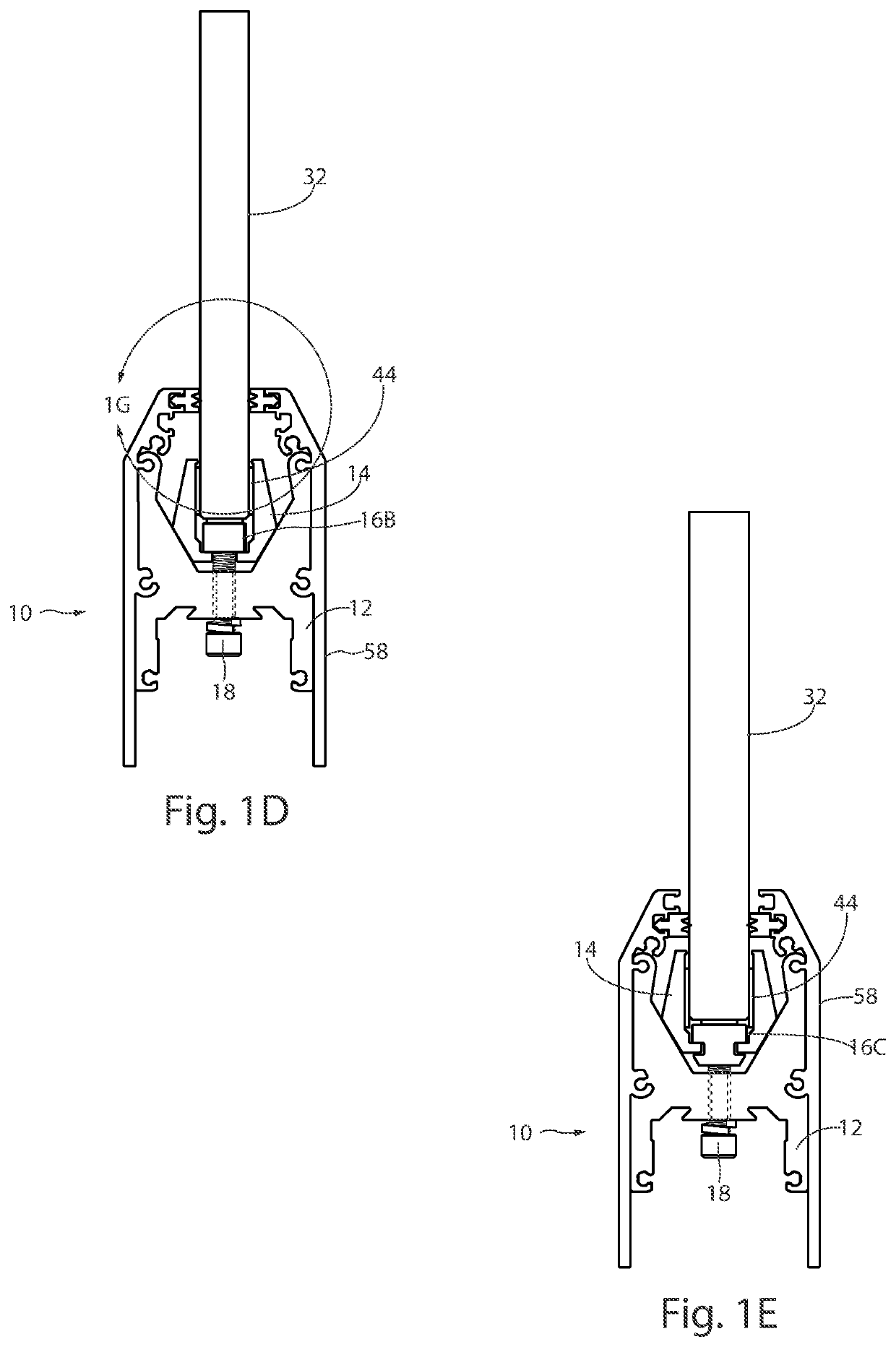
[0006]The door rail system of the present invention improves upon the door rail system disclosed in U.S. Pat. Nos. 6,434,905 and 6,912,818 by adding new features that, among other things, provide the ability to readily and more efficiently accommodate varying doorway widths using cut-to-fit modular side covers and standard core rails, readily install side covers having a variety of heights, profiles, and finishes, readily accommodate a variety of panel thicknesses, and, provide angular and axial adjustment of a door with respect to a door jamb and adjacent doors. The new door rail system also includes an accessory channel having the ability to hold concealed within the rails, additional door hardware such as alignment devices and locking devices.

Problems solved by technology

Such means of attachment make it difficult or impossible to remove the rail from the glass panel, once installed.
This is generally considered to be a disadvantage of adhesively attached rail designs as the rail cannot readily be removed for replacement due to scuffing or other damage, or for other needed repair.
While the system of Applicant's prior patents has proven successful, it lacks the efficiency of combining cut-to-fit modular side covers with a plurality of standard core rails that, together, are able to span varying doorway widths, the ability to readily accommodate a variety of panel thicknesses without changing multiple components, and the ability to provide angular adjustment of a door with respect to a door jamb or adjacent door.

Method used


Image

  • Door Rail System
  • Door Rail System
  • Door Rail System

Examples


Embodiment Construction

[0060]The present invention will now be described more fully hereinafter with reference to the accompanying drawings, in which preferred embodiments of the invention are shown. The invention however, may be embodied in many different forms and should not be construed as being limited to the embodiments set forth herein. Rather these embodiments are provided so that this disclosure will be thorough and complete, and will fully convey the scope of the invention to those skilled in the art. Like numbers refer to like elements throughout.

[0061]Wherever used, the terms “comprises,”“comprising,”“includes,”“including,”“has,”“having,” or any other variation thereof, are intended to cover a non-exclusive inclusion. For example, processes, methods, articles, or apparatuses that comprise a list of elements are not necessarily limited to only those elements but may include other elements not expressly listed or inherent to such processes, methods, articles, or apparatuses. Further, unless expre...


PUM

PropertyMeasurementUnit
clamping forceaaaaaaaaaa
perimeteraaaaaaaaaa
thicknessesaaaaaaaaaa

Abstract

An improved door rail system for holding a panel, such as a glass panel, is presented. The door rail system includes a core rail and clamping rails having a wedging geometry so that when the clamping rails are actuated with respect to the core rail, clamping force is applied to the glass panel to secure the panel within the core rail. The improved door rail system accommodates panels of varying thickness, features the use of modular side covers and incorporates a door to door jamb adjustment device allowing for angular adjustments.

Description

CLAIM FOR PRIORITY[0001]This application claims priority as a continuation of U.S. application Ser. No. 16 / 932,643 entitled “Improved Door Rail System,” filed on Jul. 17, 2020, the contents of which are incorporated herein, in their entirety.BACKGROUND OF THE INVENTIONField of the Invention[0002]The present invention is directed generally to the field of doors and, more particularly, to an improved rail system for framing a panel for use as a door.Background Art[0003]Door rail systems are commonly used to hold or frame one or more panels, including glass, metal, fiberglass, wood, vinyl (and other polymers), or composite panels, in a doorway opening. Typically, upper and lower horizontal rails are used to secure a panel at its upper and lower horizontal edges.[0004]In many prior art rail systems, such as those commonly used in the glass doors of large office buildings and shopping malls, the rails are attached to the glass panel using structural adhesives. Such means of attachment ma...

Claims


Application Information

Patent Timeline
Patent Type & Authority Applications(United States)
IPC IPC(8): E06B3/58E06B3/54
CPCE06B3/5864E06B3/5454E06B3/305E06B3/306E06B2003/6223E06B3/72E06B2003/7046E06B3/36
Inventor MOURCHID, NAOUFEL
Owner C R LAURENCE
Why Eureka
Try Eureka