System and method for forming a container having a grip region

a technology of container and grip, which is applied in the direction of rigid containers, transportation and packaging, and other domestic objects, can solve the problems of affecting the performance of the container at certain areas, affecting the ability, and the plastic material is less able to flow and stretch around the protruding protruding, so as to achieve secure grippability and reduce the effect of weight and good ergonomic feel in the resultant container

Active Publication Date: 2007-10-11
CO2 PAC
View PDF99 Cites 100 Cited by
  • Summary
  • Abstract
  • Description
  • Claims
  • Application Information

AI Technical Summary

Benefits of technology

[0009] One aspect of the invention is to create a deep-set grip in a container that provides secure grippability along with a good ergonomic feel in the resultant container. In a preferred embodiment, the deep-set grip is achieved in a manner to maintain the overall container weight at an as minimal a weight as possible, and to allow for a wide range of design applications.

Problems solved by technology

One problem with stretch blow molding is that stretching of the plastic material may affect the performance of the container at certain areas.
While the stretching of the plastic material may not cause problems for most sections of the container, it particularly affects the ability of the plastic material to form around a deep protrusion in the mold.
However, the plastic material is less able to flow and stretch around the protrusion because of the contact friction with the moid surface.
A lack of definition in the base caused by the inability of the plastic to properly form at a deep protrusion is a particular problem.
While this is a particular problem in the base region, similar problems exist in other regions of a container where an inset is positioned.
These problems can exist with any forming process, such as blow molding, where material must flow around a protrusion of a mold to form an inset region of a container.
When blowing deep-set grips with known blow molding processes, plastic material becomes trapped in the grip regions consequently starving other regions of the container of material.
Alternatively, design compromises are made so that the resultant thinner regions are closer to the axis of the container causing those regions to be blown with more material.
However, blowing heavier containers and the resultant design constraints do not solve the problem described above.

Method used


Image

  • System and method for forming a container having a grip region
  • System and method for forming a container having a grip region
  • System and method for forming a container having a grip region

Examples


Embodiment Construction

[0029] Exemplary embodiments of the invention are discussed in detail below. In describing the exemplary embodiments, specific terminology is employed for the sake of clarity. However, the invention is not intended to be limited to the specific terminology so selected. While specific exemplary embodiments are discussed, it should be understood that this is done for illustration purposes only. A person skilled in the relevant art will recognize that other components and configurations may be used without parting from the spirit and scope of the invention. All references cited herein are incorporated by reference as if each had been individually incorporated.

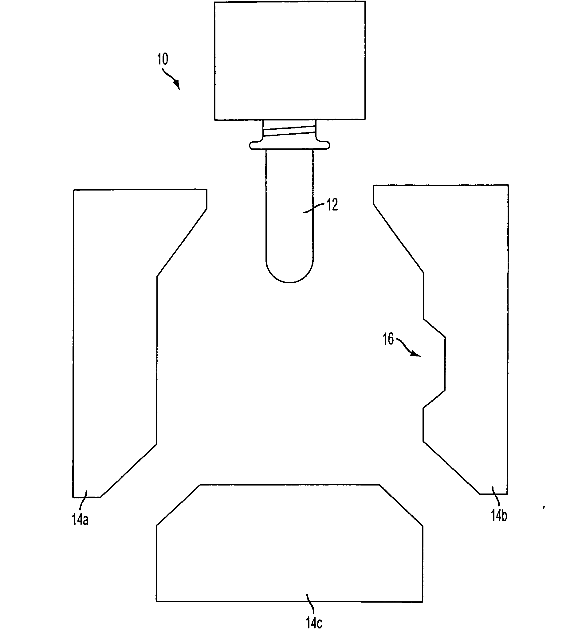
[0030] Exemplary embodiments of the present invention may generally relate to a container, a method of inverting a grip of a container, and a blow molding apparatus for forming a container having an invertible grip. In an exemplary embodiment, as shown in FIG. 4, a blow-molding apparatus 10 may receive a parison 12 and enclose th...


PUM

PropertyMeasurementUnit
crystallinityaaaaaaaaaa
surface areaaaaaaaaaaa
shapeaaaaaaaaaa

Abstract

A container forming assembly and method includes receiving a parison within a cavity of a mold, enclosing the parison within the mold having a wall with a recess, inflating the parison in the mold to form a blow molded container where the blow molded container has a sidewall, a movable region formed at the recess, and a hinge circumscribing an interface between the sidewall and the movable region, and moving the movable region toward an interior of the blow molded container about the hinge before filling.

Description

BACKGROUND OF THE INVENTION [0001] 1. Field of the Invention [0002] The invention generally relates to a method for blow molding a container, and more particularly to a method for blow molding a container to be formed with deep-set grips so that the formed container has secure grippability along with a good ergonomic feel. [0003] 2. Related Art [0004] One method of manufacturing containers is through a process known as stretch blow molding. In this process, a preformed parison, or preform, is prepared from a thermoplastic material, typically by an injection molding process. The preform typically includes a threaded end, which becomes the threads of the container. During stretch blow molding, the preform is positioned between two open blow mold halves. The blow mold halves close about the preform and cooperate to provide a cavity into which the preform is blown to form the container. Once the mold is closed, a gas is forced into the perform causing it to stretch and to take the shape...

Claims


Application Information

Patent Timeline
Patent Type & Authority Applications(United States)
IPC IPC(8): B29C49/00
CPCB29B2911/1402B65D23/102B29B2911/14033B29B2911/1404B29C49/06B29C49/22B29C49/4802B29C49/54B29K2023/06B29K2023/0633B29K2023/065B29K2023/086B29K2067/00B29K2077/00B29L2031/463B29L2031/7158B29B2911/14026B29C2949/28B29C2949/26B29C2949/24B29C2949/22B29C2949/0715
Inventor TRUDE, GREGORYKELLEY, PAUL
Owner CO2 PAC
Why Eureka
Try Eureka