
Method and system of using electromagnetism to control fertilizer leaching

a technology of electromagnetism and fertilizer leaching, applied in the direction of magnetic separation, lorentz force separation, contaminated groundwater/leachate treatment, etc., can solve the problems of reducing normal soil microbes, nitrate and phosphate leaching, and nitrate and phosphate can be particularly difficult to remove, so as to reduce the amount of excess fertilizer and reduce the cost , the effect of efficient fertilizer application

Active Publication Date: 2018-11-20
ROSSI TIMOTHY JAMES
View PDF17 Cites 0 Cited by
  • Summary
  • Abstract
  • Description
  • Claims
  • Application Information

AI Technical Summary

Benefits of technology

The invention helps reduce excess fertilizer in the groundwater and environment by using electromagnetic technology to decrease the movement of negative charged species like nitrate, phosphate, and sulfate. This results in cost savings, more efficient application of fertilizers to plants, easier compliance with regulatory policies, and easy management of field installation.

Problems solved by technology

Fertilizer leaching is a major problem for the agricultural industry, a headache for most growers, a challenge for fertilizer companies, and a serious concern to public health and the future of our environment.
Nitrate and phosphate can be particularly difficult, with some ground water used for public drinking having nitrate concentrations of up to 2000 parts per million (ppm).
Such increased concentrations can lead to decreases in normal soil microbes, thereby decreasing nitrogen fixation, particularly by non-leguminous plants.
There is approximately 1 million tons of nitrogen fertilizer currently in the ground, and within about 10 to about 50 years, this may hit the groundwater and produce environmental and societal disruption.
Additionally, by increasing extracting ground water, there can be salt intrusion into well water, and produce health problems.
Therefore, for all negatively charged fertilizer formulations entering the soil, this natural mechanism will not be effective and another mechanism is needed.
Magnetic Fields generated by electrical currents can be produced by Alternating Currents (AC) or Direct Currents (DC), but there are differences and limitations between them.

Method used


Image

  • Method and system of using electromagnetism to control fertilizer leaching
  • Method and system of using electromagnetism to control fertilizer leaching
  • Method and system of using electromagnetism to control fertilizer leaching

Examples


example 1

al Conductor

[0140]FIG. 6 depicts an embodiment of a device 600 for creating a magnetic field using electric current through a conductor. Cylindrical conductor (inner column) 605 is surrounded by insulator 610. Electric current 615 flows through conductor 605, producing circumferential magnetic field lines 620 induced by current 615.

example 2

Conductor

[0141]FIG. 7 depicts an alternative embodiment 700 in which conductive material 705 is in the form of a torus (doughnut). Electric current 710 flows through conductor 705, producing magnetic field lines 715 induced by current 705.

[0142]As shown in FIG. 7, a vertical center line represents a vertical conductor placed within a moisture impermeable pipe, carrying an electromagnetic current. The elliptical lines represent the direction of the magnetic field lines and the force on ions or ionic compounds, such as nitrate, during the application of fertilizer delivered within the pipe.

[0143]In an embodiment, the vertical conductor is formed of 10 gauge iron wire and the pipe is formed of one-inch PVC pipe. In alternative embodiments, the design may include other conductive materials and may be different in diameter, and pipes may include alternative moisture impermeable materials and diameters, such as a rubber hose casing to replace the PVC.

[0144]Electric charges in motion form ...

example 3

ation in a 40″ Bed

[0147]On an average 40″ bed volume of soil, about 260 square inches are available to work with when determining field placement and flux. Magnetic flux is magnetic field times the area, so it consists of two pieces, the size of the magnetic field and the size of the area in which it is acting.

[0148]FIG. 8 illustrates an embodiment 800 according to the present invention on a 40″ bed. This embodiment comprises using electrically conductive wire 805. In an embodiment, conductive wire 805 (represented by the vertical and horizontal straight lines and vertical hashed lines), are run through a moisture impermeable pipe (not shown) Electrical current flowing through the conductive wire 805 produces magnetic field lines 810. The conductive wire 805 is insulated by PVC pipe or hose for field safety and to avoid a short circuit (since conductive wires cannot have direct contact with irrigation water). There are 4 inches that are not shown on each side of the trapezoid depict...


PUM

PropertyMeasurementUnit
lengthaaaaaaaaaa
frequencyaaaaaaaaaa
magnetic fieldsaaaaaaaaaa

Abstract

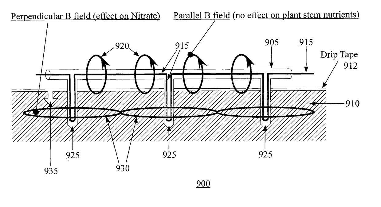
Devices are provided comprising one or more insulated hollow vertical pipes inserted into a bed of soil, each pipe having a descending and an ascending conductive element forming a loop within the interior of the pipe. A plurality of such vertical pipes can be attached to a straight pipe, forming a two dimensional array of vertical pipes, in which the loops are connected in series. Further, a series of such one-dimensional straight pipes can be attached together to provide a two-dimensional array. When vertical pipes are inserted into the bed of soil and an electrical current applied to the array, one or more magnetic fields is produced within the bed and parallel to the surface of the bed. The magnetic fields so produced impede downward flow of ionic fertilizers into the ground water, and retaining the fertilizer near growing plants when the bed is irrigated.

Description

CLAIM OF PRIORITY[0001]This application is a Continuation claiming priority to U.S. application Ser. No. 15 / 176,923 filed 8 Jun. 2016 (Now U.S. Pat. No. 9,707,568), which is a Continuation claiming priority to International Patent Application No. PCT / US2014 / 070094 filed 12 Dec. 12, 2014, which claims priority to U.S. Provisional Patent Application No. 61 / 915,967, filed 13 Dec. 2013, entitled “Method and System for Using Electromagnetism and Alternating Current to Control Fertilizer Leaching,” Timothy James Rossi, inventor. These applications and patent are herein incorporated fully by reference.BACKGROUND[0002]Fertilizer leaching is a major problem for the agricultural industry, a headache for most growers, a challenge for fertilizer companies, and a serious concern to public health and the future of our environment.BRIEF DESCRIPTION OF THE FIGURES[0003]Aspects of this invention are described with reference to specific embodiments thereof. Other features of this invention can be app...

Claims


Application Information

Patent Timeline
Patent Type & Authority Patents(United States)
IPC IPC(8): B03C1/023B03C1/28C02F1/48C02F101/10C02F101/16C02F103/06
CPCB03C1/286B03C1/023B03C2201/22B09C2101/00C02F2201/48C02F2101/101C02F2101/105C02F2101/163C02F2103/06C02F1/487
Inventor ROSSI, TIMOTHY JAMES
Owner ROSSI TIMOTHY JAMES
Learn More