Material erosion monitoring system and method

a monitoring system and material technology, applied in the field of systems and methods for evaluating the status of materials, can solve the problems of difficult to create accurate estimates of the expected lifetime of the furnace, no well-established method of deterministically measuring the thickness and and the inability to accurately measure the thickness of the erosion profile of the walls of such furnaces. to achieve the effect of reducing the level of clutter

Active Publication Date: 2015-10-01
PANERATECH
View PDF20 Cites 222 Cited by
  • Summary
  • Abstract
  • Description
  • Claims
  • Application Information

AI Technical Summary

Benefits of technology

[0009]An improved system and method to evaluate the status of a material is disclosed herein. One or more aspects of exemplary embodiments provide advantages while avoiding disadvantages of the prior art. The system and method are operative to identify flaws and measure the erosion profile and thickness of different materials, including refractory materials, using electromagnetic waves. The system is designed to reduce a plurality of reflections associated with the propagation of electromagnetic waves launched into the material under evaluation, by a sufficient extent so as to enable detection of electromagnetic waves of interest reflected from remote discontinuities of the material. Furthermore, the system and method utilize a configuration and signal processing techniques that reduce clutter and enable the isolation of electromagnetic waves of interest. Moreover, the launcher used in the system is impedance matched to the material under evaluation, and the feeding mechanism is designed to mitigate multiple reflection effects to further suppress clutter.
[0011]The system also includes an electromagnetic wave launcher designed and adapted to reduce a plurality of reflections that significantly contribute to the clutter received by the computer-based processor. The launcher provides levels of clutter reduction by a sufficient extent so as to enable detection of electromagnetic waves of interest that otherwise might not be possible. The launcher may be used in evaluation of the refractory walls of hot furnaces to create an erosion profile of the surface of the inner walls in an operational furnace.
[0013]By significantly reducing the level of clutter caused by reflections and ringing of propagating electromagnetic waves, as compared to standard techniques, and by determining the location of remote discontinuities from the material under evaluation, the system and method are able to identify flaws and measure the erosion profile of the remote surface of such material.

Problems solved by technology

However, the inner walls of the refractory chamber of the furnace will degrade during operation.
The effects of this degradation include inner surface erosion, stress cracks, and refractory material diffusion into the molten material.
Currently, there is no well-established method of deterministically measuring the thickness and erosion profile of the walls of such furnaces.
As a result, manufacturers experience either an unexpected leakage of molten material through the furnace wall or conservatively shut down the furnace for re-build to reduce the likelihood of any potential leakage, based on the manufacturer's experience of the expected lifetime of the furnace.
Each of these factors is subject to uncertainties that make it difficult to create accurate estimates of the expected lifetime of a furnace.
Moreover, the flow of molten material, such as molten glass, at high temperatures erodes and degrades the inner surface of the refractory material and creates a high risk for molten glass leakage through the refractory wall.
A major leak of molten glass through the gaps and cracks in the furnace walls may require at least 30 days of production disruption before the furnace can be restored to operating mode because it needs to be cooled down, repaired, and fired up again.
Furthermore, a leak of molten glass may cause significant damage to the equipment around the furnace and, most importantly, put at risk the health and life of workers.
This leads to significant costs for manufacturers in terms of their initial investment and the reduced production capacity over the operational life of the furnace.
Another important issue is that the material used to build the refractory chamber of the furnace may have internal flaws not visible by surface inspection.
This could translate into a shorter life of the furnace and pose serious risks during furnace operation.
However, these efforts have faced certain challenges and limitations.
In particular, attempts made to determine furnace wall thickness on hot furnaces have been generally unsuccessful because of the large signal losses involved in evaluating the inner surface of refractory materials, especially at relatively high frequency bands.
Likewise, at relatively low frequency bands signals still experience losses and are limited in terms of the bandwidth and resolution required by existing systems.
Moreover, in placing system components close to the surface of the refractory material to be evaluated, spurious signal reflections make it difficult to isolate the reflected signal of interest, thus further complicating the evaluation of the status of either the inner surface or the interior of such materials.
A major challenge is that furnace walls become more electrically conductive as temperature increases.
Therefore, signals going through a hot furnace wall experience significant losses making the detection of these signals very challenging.

Method used


Image

  • Material erosion monitoring system and method
  • Material erosion monitoring system and method
  • Material erosion monitoring system and method

Examples


Embodiment Construction

[0023]The following description is of a particular embodiment of the invention, set out to enable one to practice an implementation of the invention, and is not intended to limit the preferred embodiment, but to serve as a particular example thereof. Those skilled in the art should appreciate that they may readily use the conception and specific embodiments disclosed as a basis for modifying or designing other methods and systems for carrying out the same purposes of the present invention. Those skilled in the art should also realize that such equivalent assemblies do not depart from the spirit and scope of the invention in its broadest form.

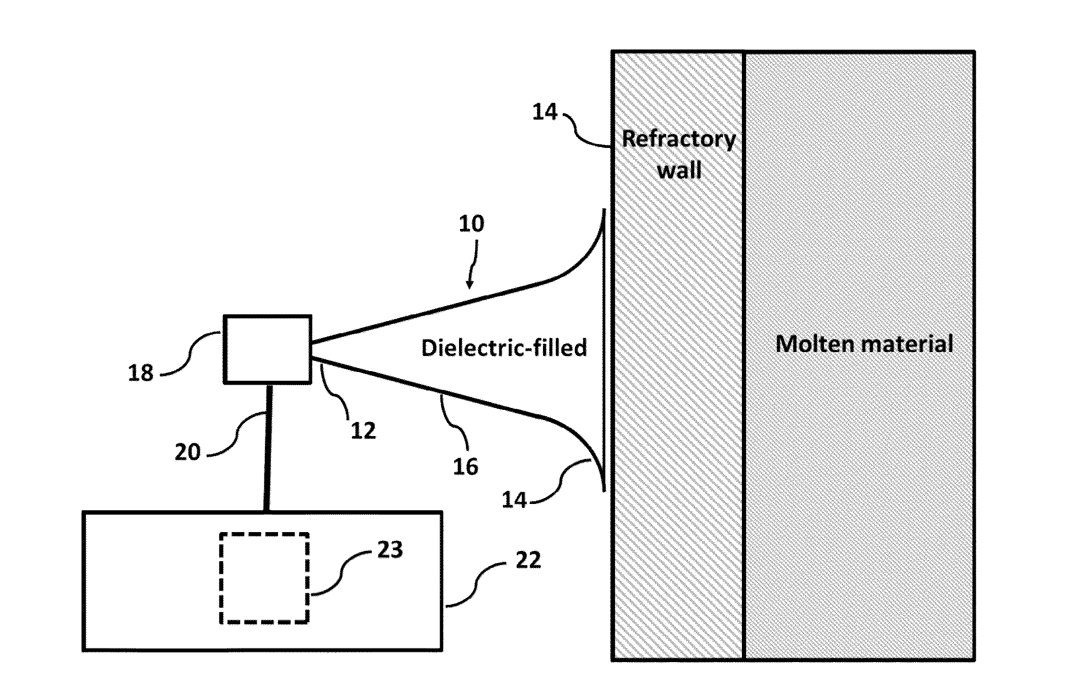
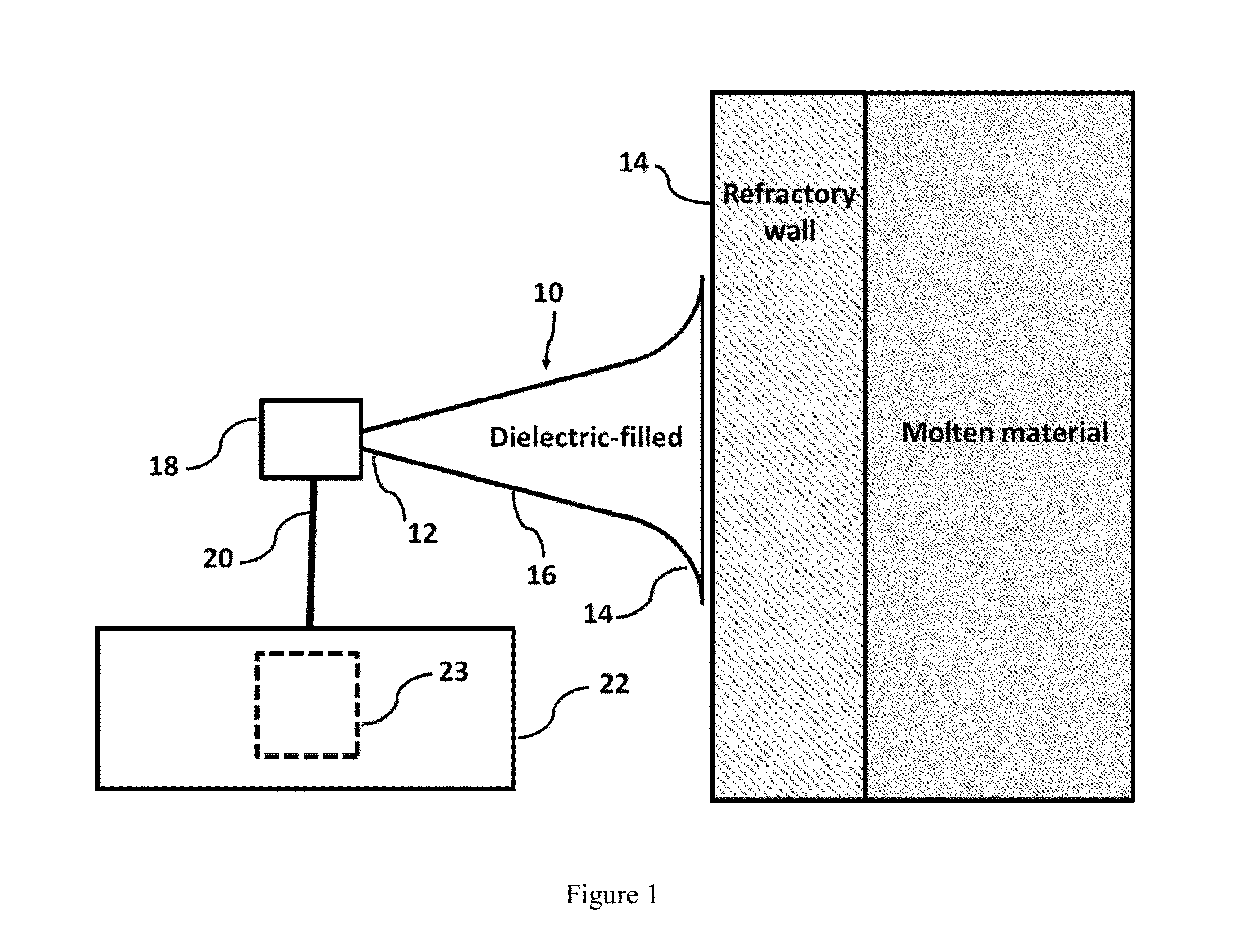
[0024]In accordance with certain aspects of an embodiment of the invention, a material evaluation system is shown in FIG. 1. The system is configured to evaluate a status of a refractory material used as a furnace wall. Thus, the refractory material has an outer surface and an inner surface opposite the outer surface. The inner surface of the re...


PUM

PropertyMeasurementUnit
frequencyaaaaaaaaaa
frequencyaaaaaaaaaa
frequencyaaaaaaaaaa

Abstract

Disclosed is an improved system and method to evaluate the status of a material. The system and method are operative to identify flaws and measure the erosion profile and thickness of different materials, including refractory materials, using electromagnetic waves. The system is designed to reduce a plurality of reflections, associated with the propagation of electromagnetic waves launched into the material under evaluation, by a sufficient extent so as to enable detection of electromagnetic waves of interest reflected from remote discontinuities of the material. Furthermore, the system and method utilize a configuration and signal processing techniques that reduce clutter and enable the isolation of electromagnetic waves of interest. Moreover, the launcher is impedance matched to the material under evaluation, and the feeding mechanism is designed to mitigate multiple reflection effects to further suppress clutter.

Description

GOVERNMENT LICENSE RIGHTS[0001]This invention was made with Government support under SBIR Phase II Grant No. IIP-1256254 awarded by the National Science Foundation. The Government has certain rights in the invention.FIELD OF THE INVENTION[0002]The present invention relates to systems and methods for evaluating the status of a material. More particularly, the present invention relates to systems and methods for determining refractory bricks-material interface using electromagnetic waves.BACKGROUND OF THE INVENTION[0003]Evaluation methods and systems exist within various industries for measuring the properties during and after formation of certain materials. The surface characteristics, internal homogeneity, and thickness of a material are some of the important attributes that may require evaluation. In particular, the wall thickness of glass and plastic containers using non-contact reflective and / or absorptive techniques by deploying sensors and emitters to direct radiation towards t...

Claims


Application Information

Patent Timeline
Patent Type & Authority Applications(United States)
IPC IPC(8): G01N17/02G01B7/06G01N27/61G01N22/02G01N22/00G01S13/88
CPCG01N17/02G01B7/06G01N27/61G01B15/02F27D21/0021G01N33/388G01N22/02
Inventor RUEGE, ALEXANDER C.BAYRAM, YAKUPWALTON, ERIC K.
Owner PANERATECH
Why Eureka
Try Eureka