Override Of Nonoccupancy Status In a Thermostat Device Based Upon Analysis Of Recent Patterns Of Occupancy

a technology of non-occupancy status and thermostat, which is applied in the field of environmental control systems, can solve the problems of inconvenience for guests, inability to accurately detect occupancy, and large expense of environmental control, and achieve the effect of saving energy

Active Publication Date: 2010-01-28
VERDANT ENVIRONMENTAL TECH INC
View PDF4 Cites 228 Cited by
  • Summary
  • Abstract
  • Description
  • Claims
  • Application Information

AI Technical Summary

Benefits of technology

[0006]Therefore, there is a need for a mechanism that reduces, during certain identified periods of time, the chance of wrongly turning off a heating, cooling, or ventilation system due to a missed signal of occupancy, or due to a prolonged period of inactivity by an occupant, while still allowing for energy savings made possible by general utilization of a motion detector or occupancy sensor.

Problems solved by technology

Energy usage for environmental control, especially for heating or cooling, is a major expense in many homes and businesses.
The mechanism for sensing occupancy may however not be perfectly accurate.
That is, a person may be in the conditioned space served by a heating, cooling or ventilation system, and potentially not be detected by an occupancy sensor, or at least not detected for some period of time.
This might be caused by a chosen mechanism for sensing occupancy which is not sensitive enough, or a person might be hidden from the “view” of the occupancy sensor.
If a heater or air-conditioner were erroneously turned off, it could possibly cause discomfort to a guest, especially at night when the temperature might become quite uncomfortable before the guest awakes enough to correct it.
In a motel room, even just mild discomfort might be something that is quite undesirable to the business.
The possibility of wrongly determining a nonoccupancy condition might occur more often during certain periods of the day.

Method used


Image

  • Override Of Nonoccupancy Status In a Thermostat Device Based Upon Analysis Of Recent Patterns Of Occupancy
  • Override Of Nonoccupancy Status In a Thermostat Device Based Upon Analysis Of Recent Patterns Of Occupancy
  • Override Of Nonoccupancy Status In a Thermostat Device Based Upon Analysis Of Recent Patterns Of Occupancy

Examples


Embodiment Construction

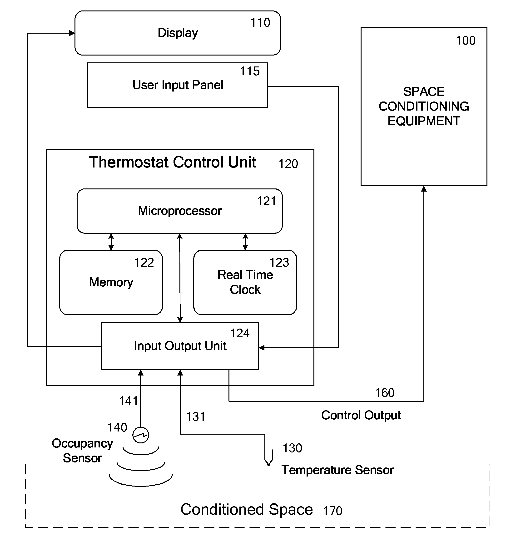
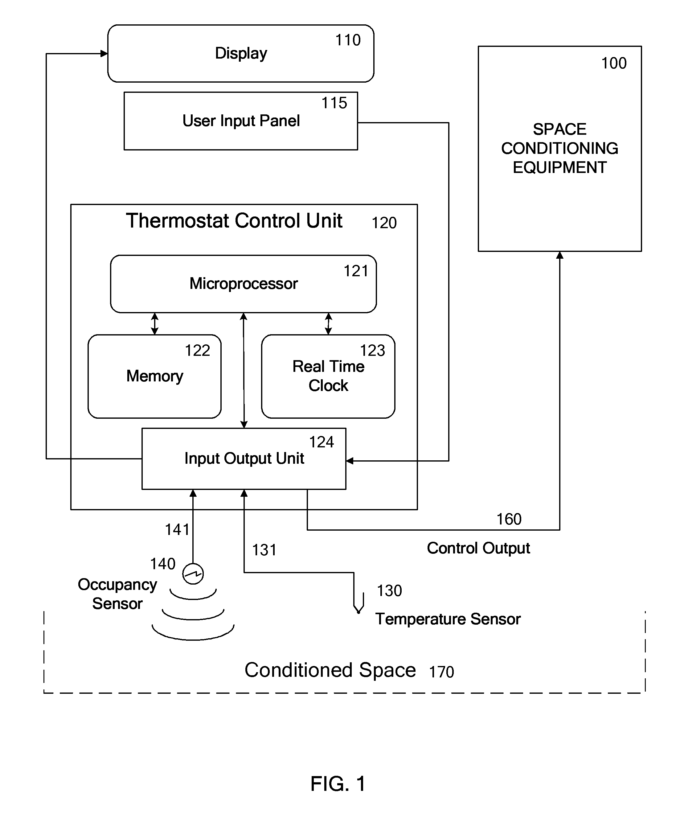
[0023]An illustrated embodiment of the subject invention provides a control apparatus which may be a thermostat apparatus or other HVAC control system, which might be centralized or distributed, that incorporates an occupancy sensor and which may include also a temperature sensor, a display screen, and / or a user input mechanism. The control process of the thermostat, or the control system, provides for running a control program such as a normal event driven program that determines, typically at user programmed times, a setpoint temperature for further use by the thermostat in controlling the space conditioning equipment.

[0024]In the following discussion and description of an illustrated embodiment of the invention, the thermostat or control apparatus as described may incorporate a thermostat control program which implements some features of the invention, or a box which includes a thermostat for control of a part of an HVAC system may be controlled or take inputs that affect the con...


PUM


Abstract

A thermostat system with a thermostat control program is disclosed for controlling a Heating Ventilation and/or Air Conditioning (HVAC) system which incorporates a mechanism for detecting activity or occupancy in a room, area or conditioned space served by the HVAC system. The thermostat control program analyzes levels, counts or other aspects of activity detected in the conditioned space, with an operating sequence which may include pattern recognition techniques. The operating sequence of the thermostat control program may further depend upon time of day, and upon periods of time identified as being periods for special handling of occupancy, or the recognition of occupancy. These factors may then be utilized by the thermostat control program to influence determination of the temperature setpoint, or to select from alternative programming provided either by the user of the thermostat, or by factory programming, with purpose of balancing energy savings and comfort.

Description

BACKGROUND OF THE INVENTION[0001]This invention relates to the art of environmental control systems, to the art of thermostats which control heating, ventilation and cooling systems, and more particularly to those thermostats which incorporate a motion detector or occupancy sensor. Additional related fields of art include electric heating, electric heaters, electric baseboard heaters, air-conditioning system control, thermostats, energy conservation, energy management, motion detectors, and occupancy sensors. Heating Ventilation and / or Air Conditioning systems are commonly referred to as HVAC units, or just HVAC.[0002]Energy usage for environmental control, especially for heating or cooling, is a major expense in many homes and businesses. Even minor changes in environmental control procedures can result in significant energy savings. Typical approaches for saving energy include such procedures as manually turning off a heating or cooling system when a room is not used, or reducing ...

Claims


Application Information

Patent Timeline
Patent Type & Authority Applications(United States)
IPC IPC(8): G05D23/00
CPCF24F11/0012G05D23/1902F24F2011/0075F24F11/0034F24F11/30F24F2110/10F24F2120/10F24F11/46F24F2120/00F24F11/63
Inventor ROSEN, HOWARD
Owner VERDANT ENVIRONMENTAL TECH INC
Why Eureka
Try Eureka