Detector controlled illuminating system

a technology of illuminating system and detector, which is applied in outdoor lighting, lighting heating/cooling arrangements, lighting applications, etc., can solve the problems of only generating useful light, and achieve the effect of reducing illuminance, reducing illuminance, and changing the mood and motivation of observers

Inactive Publication Date: 2015-02-05
SPERO YECHEZKAL EVAN
View PDF12 Cites 173 Cited by
  • Summary
  • Abstract
  • Description
  • Claims
  • Application Information

AI Technical Summary

Benefits of technology

[0031]Further objectives of the present invention are (among others) to overcome the deficiencies in the prior art and effect the following: Light is generated only when, where and in the proper amount and color that can best be used by people or is their personal preference. This will save wasted energy, money and air and light pollution while increasing visual performance and comfort. An exigency based lighting fixture is presented that provides correct illuminance in terms of chromaticity, homogeneous or aesthetic lighting generally and task lighting locally for the visual tasks at hand while preserving high visual comfort.
[0049]Visual performance models imply that virtually all tasks done in offices and schools could be done just as well at much lower illuminance than those currently used. However, illuminances have not been reduced because people like an interior to appear bright. Dim, gloomy lighting can induce a sense of visual discomfort which may change the observer's mood and motivation to carry out a task, particularly if the work is prolonged. Thus, if a perception of brightness could be maintained at a lower illuminance, energy consumption and carbon emissions could be reduced. Thus a preferred embodiment of the differentiated light delivery lighting fixture includes light sources to provide selective lighting to surfaces in the instantaneous Field of View of the occupant. The detector system has knowledge of the eye location and orientation and thus the FOV. When the fixture controller will dim in a surrounding area it will compensate for gloom by selectively illuminating a surface such as the ceiling with minimum energy to offset any negative influence on mood.

Problems solved by technology

The result of this added sophistication is that electricity is spent on generating only useful light.

Method used


Image

  • Detector controlled illuminating system
  • Detector controlled illuminating system
  • Detector controlled illuminating system

Examples


Embodiment Construction

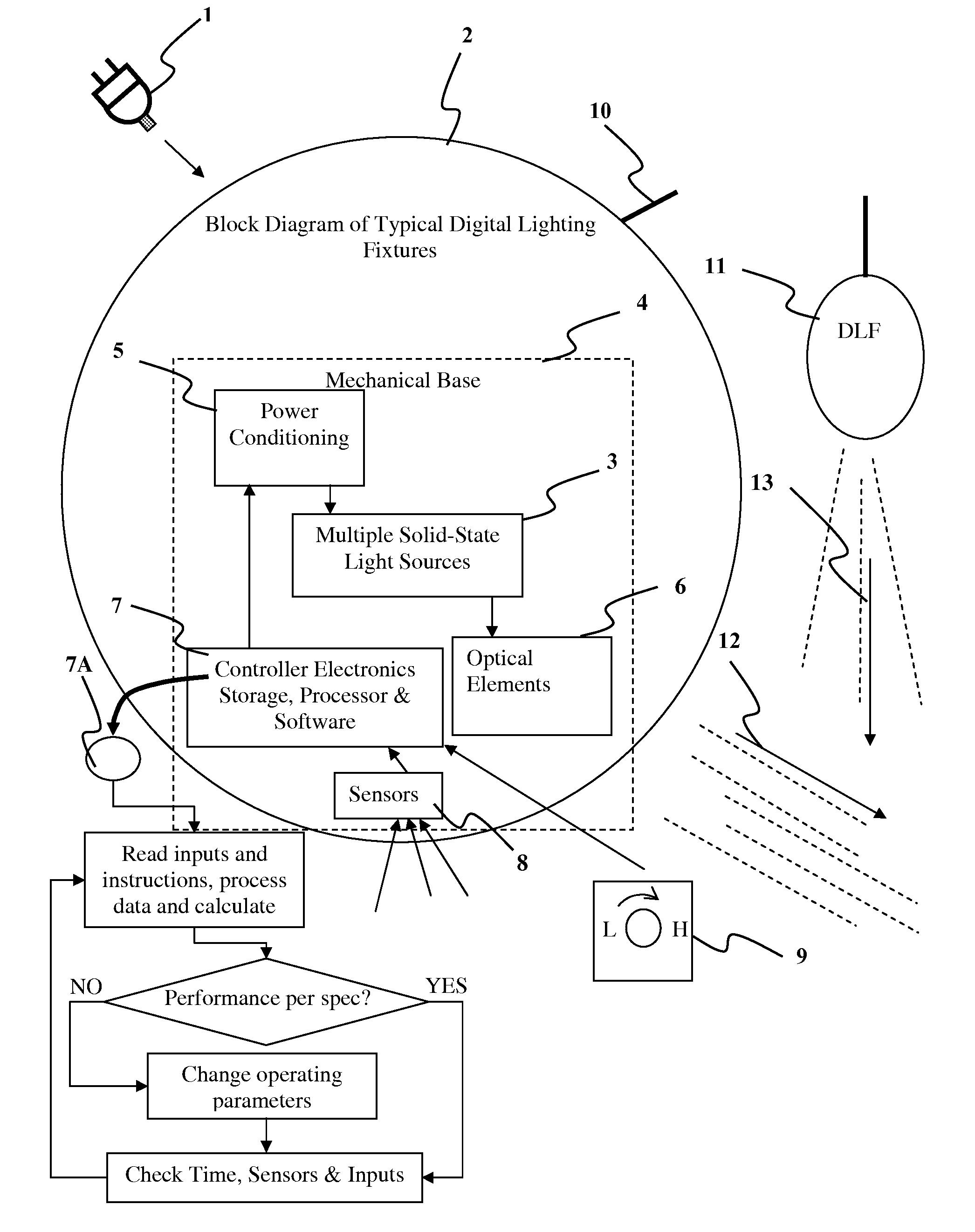
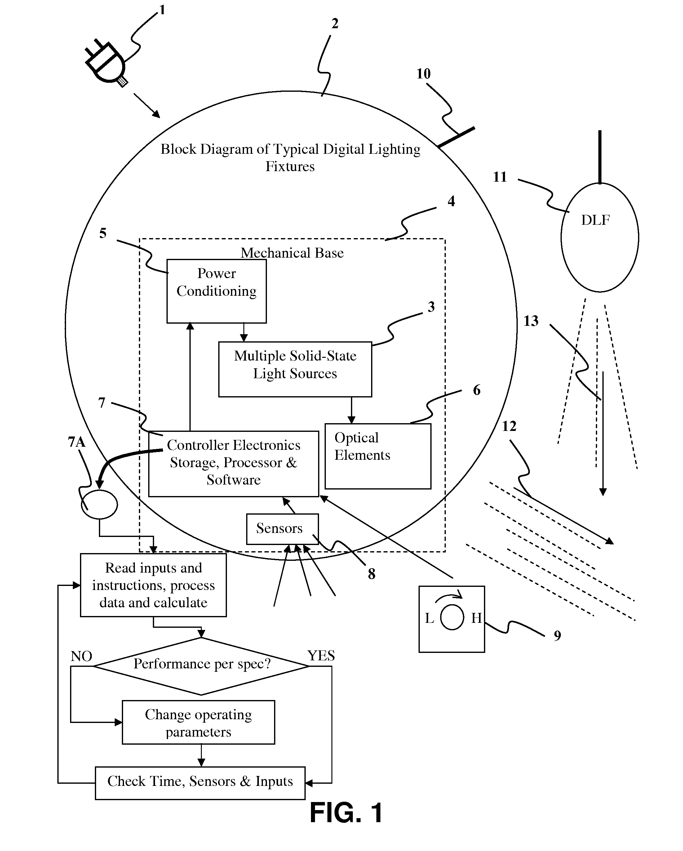
[0074]The system is built around a “digital” light source. That is, the emanating lighting effect is the sum of the characteristics of a multiplicity of discretely controllable “digit” sources. The difference between the individual “digit” light sources and their summation manifests itself in the resultant light characteristic, be in its intensity, spatial intensity distribution, spectral energy content and spectral intensity distribution. All of these characteristics are also variable with time. A light source for this purpose may be electroluminescent such as a Light Emitting Diode (LED) junction, Organic Light Emitting Diode (OLED) or carbon-related field emission devices such as a nanotube-phosphor-combination, HID, fluorescent or even an incandescent source. While a one-source lamp will not have the flexibility to effect the most correct illumination characteristics, such as maintaining correct intensity and color temperature for the lighting task at hand over changing environm...


PUM


Abstract

An illuminating device coupled with sensors or an image acquisition device and a logical controller allows illumination intensity and spectrum to be varied according to changing user needs. The system provides illumination to areas according to the principles of correct lighting practice for the optimal performance of visual tasks in the most efficient, cost effective manner. Aspects of the invention include: lighting fixtures which adapt to ambient lighting, movement, visual tasks being performed, and environmental and personal conditions affecting illumination requirements at any given instant. Lighting fixtures have spatial distribution of spectrum and intensity, providing both “background” room lighting, and “task” lighting.

Description

CROSS REFERENCE TO RELATED APPLICATIONS[0001]This application claims benefit of U.S. patent application United States Patent Application 20120206050 titled Detector Controlled Illuminating System, Filed: Jan. 24, 2012BACKGROUND OF THE INVENTIONField of the Invention[0002]The present invention is in the field of radiation producing devices. More particularly, the present invention is in the technical field of lighting fixtures. However, radiation used for headlamps, heating, night vision, UV or visible light curing, medical X-rays and other radiation uses are covered as well. General lighting fixtures otherwise known as luminaires will be used as the primary example while other irradiating devices such as infrared heaters are covered as well.DEFINITIONS, TERMS, ELEMENTS[0003]In order to clarify the intent of the present invention and its dissimilar aspects from prior art, a nomenclature system is established.[0004]Illumination: Used herein illumination refers to the deliberate applic...

Claims


Application Information

Patent Timeline
Patent Type & Authority Applications(United States)
IPC IPC(8): H05B37/02H05B3/00H05B44/00
CPCH05B37/0227H05B3/008H05B37/0218B60Q1/04B60Q1/085B60Q1/1423B60Q2300/054B60Q2300/112B60Q2300/116B60Q2300/122B60Q2300/134B60Q2300/142B60Q2300/21B60Q2300/23B60Q2300/312B60Q2300/314B60Q2300/322B60Q2300/41B60Q2300/42F21V19/02F21V21/02F21V21/30F21V23/0471F21W2111/023F21W2111/027F21W2111/08F21W2131/103F21W2131/40F21Y2113/00F21V23/0464F21V23/0478F21V29/74F21S4/28F21K9/23F21K9/232F21Y2115/10F21S41/143F21S41/147F21S41/65H05B45/20H05B47/11H05B47/10H05B47/105F21W2102/30F21W2102/18F21W2102/19F21W2102/13F21S41/153Y02B20/30Y02B20/40H05B47/115A01K1/00B60Q2900/50F21W2102/00H05B45/395
Inventor SPERO, YECHEZKAL EVAN
Owner SPERO YECHEZKAL EVAN
Why Eureka
Try Eureka