Microblinds and a method of fabrication thereof

a technology of micro-blinds and fabrication methods, applied in the field of light transmission control, can solve the problems of macro-blinds with very severe drawbacks such as cost, reliability, visual appearance, and current smart window technology, and achieve the effect of major energy saving in heating and cooling costs and better comfort for the occupants

Active Publication Date: 2010-03-23
NAT RES COUNCIL OF CANADA
View PDF8 Cites 182 Cited by
  • Summary
  • Abstract
  • Description
  • Claims
  • Application Information

AI Technical Summary

Benefits of technology

[0007]The present invention provides microblinds for windows that modify-their visible and / or infrared transmission. This allows better comfort for the occupant as well as major energy savings in terms of heating and cooling costs.
[0008]Smart windows, in accordance with embodiments of the invention, are capable of varying the transmission characteristics depending on the solar radiation, the outdoor weather conditions and the different requirements of the users (for instance, high ambient light for a meeting, low ambient light for the projection of a film).

Problems solved by technology

Current technology for smart windows, which is mainly based on the use of electrochromic layers, has severe limitations in terms of lifetime, speed, maximum IR transmission and visual aspect.
Macroblinds have also very severe drawbacks such as cost, reliability and visual appearance.

Method used


Image

  • Microblinds and a method of fabrication thereof
  • Microblinds and a method of fabrication thereof
  • Microblinds and a method of fabrication thereof

Examples


Embodiment Construction

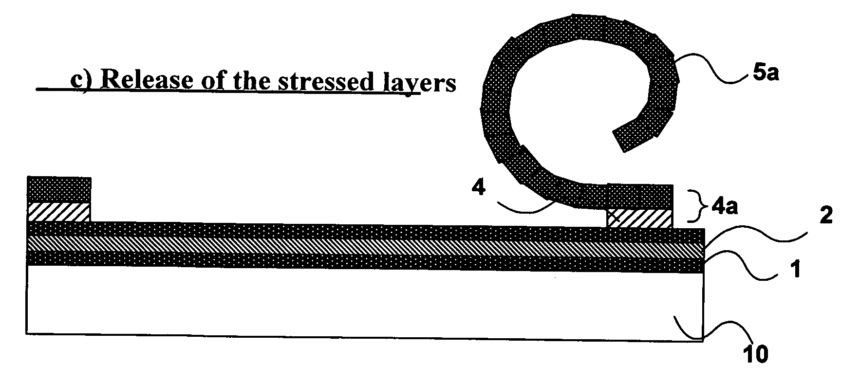
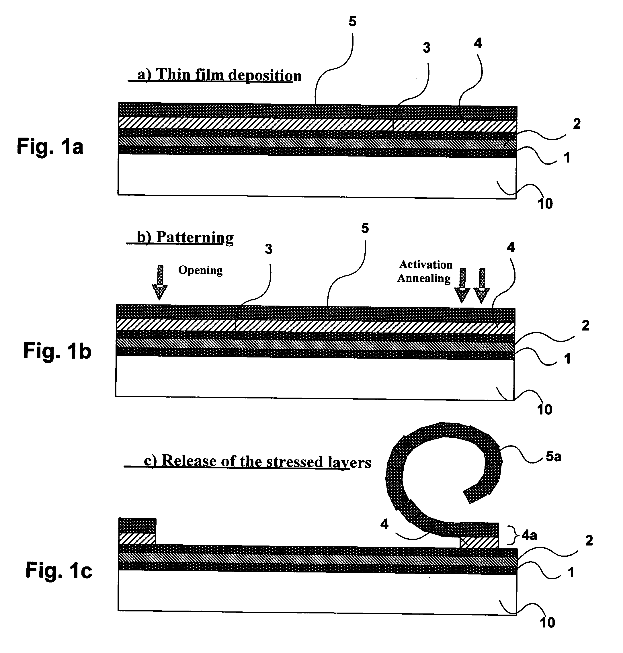
[0023]FIGS. 1a to 1c are cross-sectional views of the microblinds showing the three major fabrication steps: deposition of the thin films with a controlled stress, patterning and then release of the stressed layers. The various layer numbers are defined as a substrate 10, an insulator, a diffusion barrier and / or adhesion promoter layer 1; a transparent conducting layer 2; an insulator layer 3; a release-sacrificial-anchoring layer 4; and a reflective, resilient and stressed layer 5. The stressed layer 5 may comprise a plurality of sublayers.

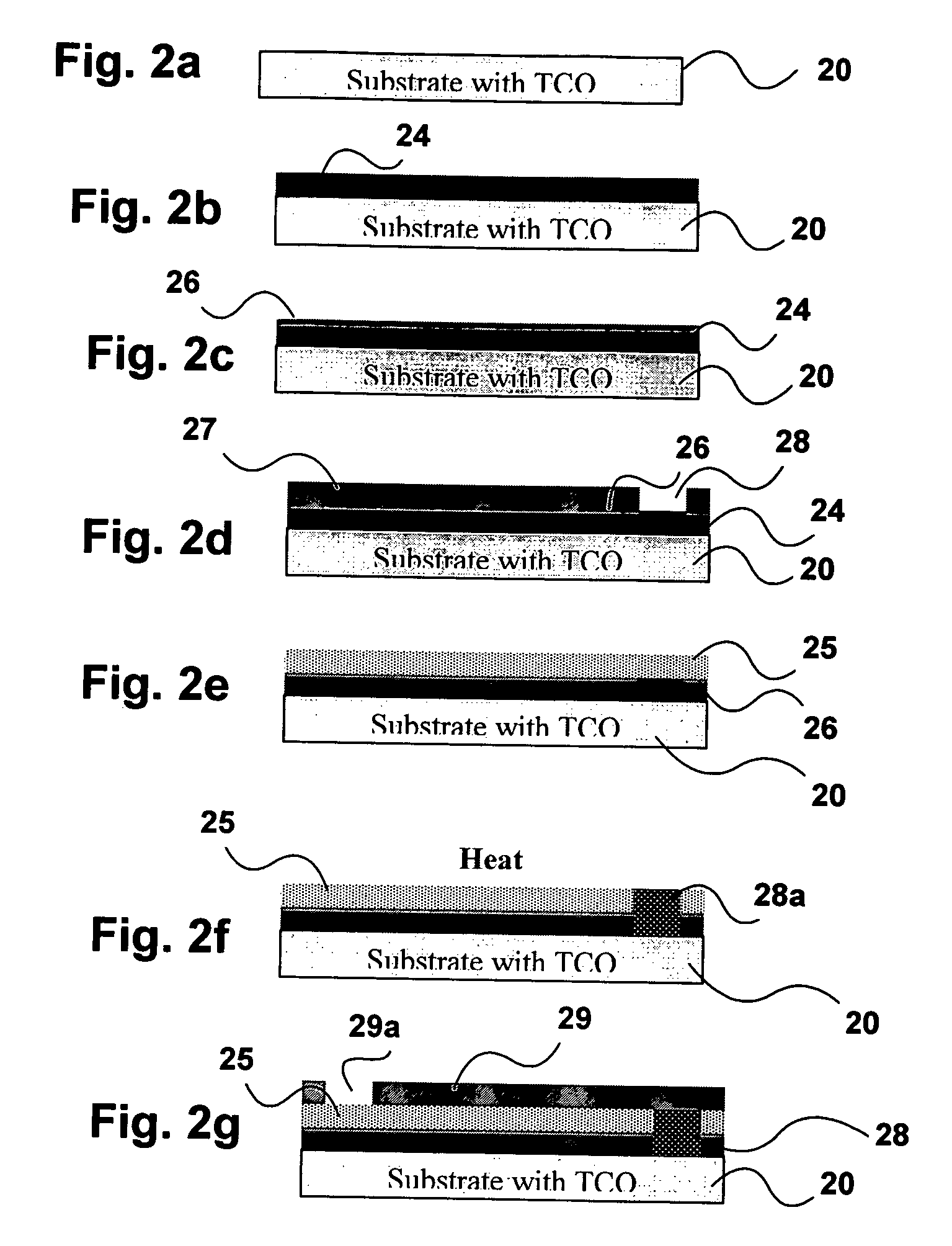
[0024]The fabrication process consists of depositing and patterning a number of layers on a clean substrate. The substrate is preferably glass but any substrate substantially transparent in the visible spectrum may also be used, including plastic foils. The process optionally comprises the deposition of a diffusion barrier, adhesion promoter and insulator layer 1 on the substrate 10, which may be a window pane, an illuminated panel, or a supporti...


PUM


Abstract

A microblind system has an array of overhanging stressed microblinds, each having an anchor portion attached a substrate and a mobile portion. The microblinds are responsive to electrostatic forces to mutate between a deployed configuration wherein the mobile portion obscure the substrate and a curled configuration wherein the mobile portion exposes the substrate. A transparent conductive layer permits the application of an electric field to the microblinds.

Description

CROSS REFERENCE TO RELATED APPLICATION[0001]This application claims the benefit of prior U.S. provisional application No. 60 / 655,447 filed on Feb. 24, 2005, the contents of which are herein incorporated by reference.FIELD OF THE INVENTION[0002]This invention relates to the field of light transmission control, and in particular to a microblind system for modifying the visible and / or infrared (IR) light transmission of surfaces, such as windows.BACKGROUND OF THE INVENTION[0003]Low emission coatings have been applied on windows to limit the transmission of IR (heat) through the windows. These coatings are very widespread; however they are characterized by fixed transmission characteristics. For optimal energy efficiency, windows should allow the transmission of IR in the winter so it contributes to heating the building, and block it in the summer to help the building stay cool. The amount of visible light should also be tuned to optimise the comfort of ambient conditions to users and m...

Claims


Application Information

Patent Timeline
Patent Type & Authority Patents(United States)
IPC IPC(8): G02B26/00
CPCG02B26/02E06B9/24
Inventor LAMONTAGNE, BORISPY, CHRISTOPHE
Owner NAT RES COUNCIL OF CANADA
Why Eureka
Try Eureka