Co-cured composite structures and method of making them

Inactive Publication Date: 2004-06-01
ROHR INC
View PDF12 Cites 179 Cited by
  • Summary
  • Abstract
  • Description
  • Claims
  • Application Information

AI Technical Summary

Benefits of technology

. Those objects should be construed to be merely illustrative of some of the more prominent features and applications of the present invention. Many other beneficial results can be attained by applying the invention in a di

Problems solved by technology

Both methods are disadvantageous in requiring costly non-reusable tooling and/or costly and tedious manufacturing steps.
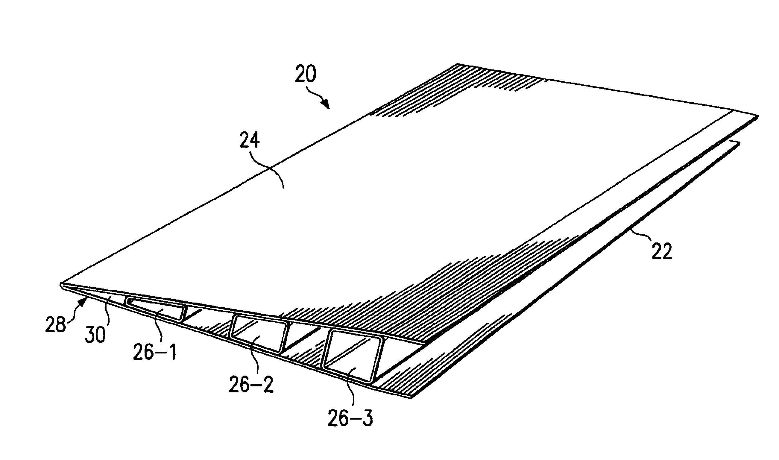
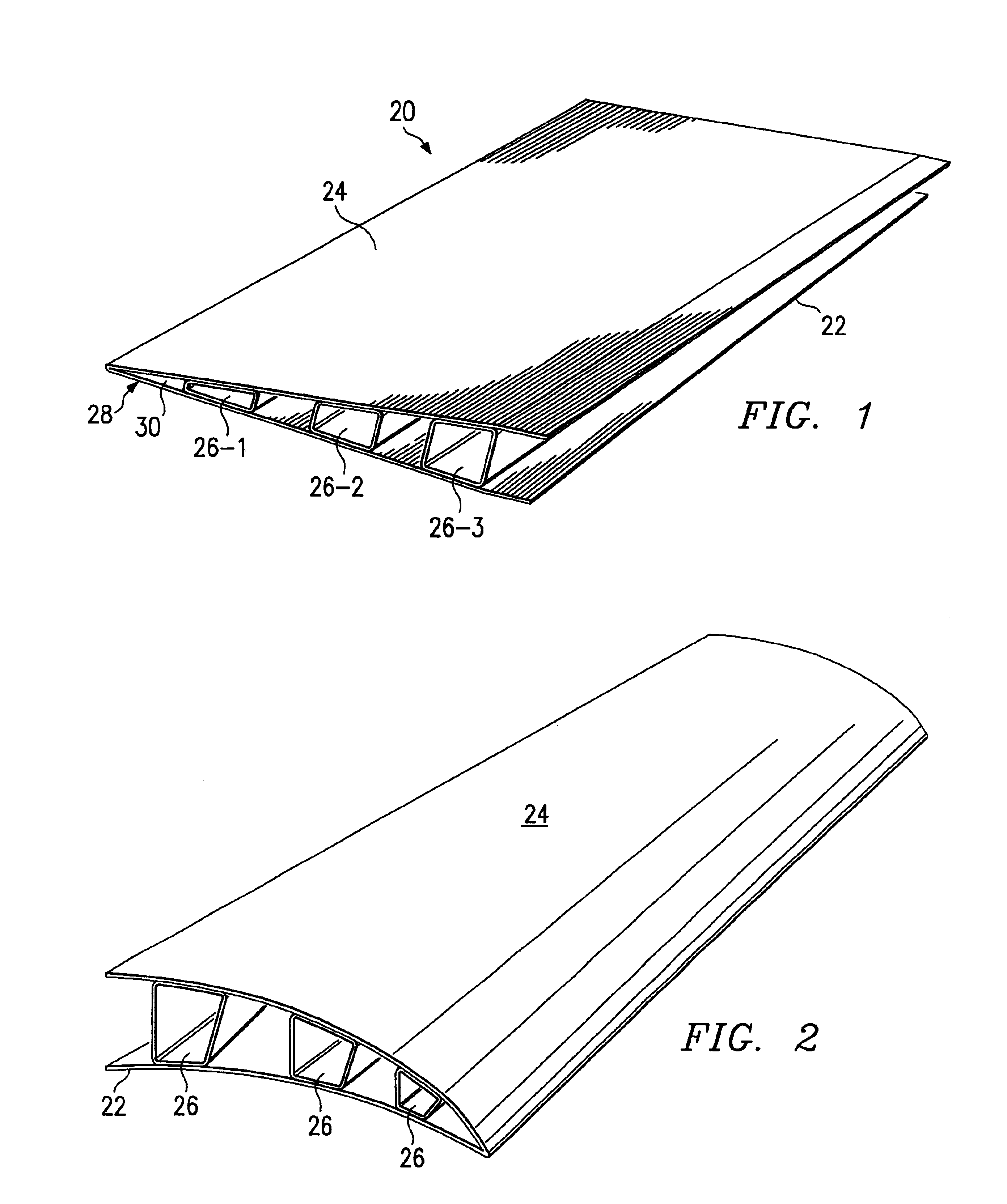
Thus, at least three very expensive and labor intensive fabrication and cure cycles have gone into the production of the exceptionally strong and lightweight composite honeycomb core sandwich panel.
At least two different and expensive tools are needed in this process.
Manufacturing flow time is very long, energy use is high, and the manufacturing floor space required is considerable.
However, co-curing an aerostructure panel has never achieved wide-spread acceptance because of a large loss of panel strength and integrity, which is due to the lack of compaction of the composite plies placed over and under the honeycomb core.
The only way to overcome this "knockdown" characteristic is to add extra plies, which creates both unwanted weight and added cost.
Thus, because of these constraints co-cured aerostructure panels are not widely manufactured in the aerospace industry.
There are other particular problems when a honeycomb core element is used to provide a stiffening element for an aerospace component.
Such flow robs resin from the laminate, introduces a weight penalty in the panel to achieve the desired performance, and forces over-design of the skin plies to account for the resin losses to the honeycomb core.
To achieve the designed performance and the corresponding laminate thickness, additional plies are necessary with resulting cost and weight penalties.
Because the weight penalty is severe in terms of the impact on vehicle performance and costly in modern aircraft a

Method used


Image

  • Co-cured composite structures and method of making them
  • Co-cured composite structures and method of making them
  • Co-cured composite structures and method of making them

Examples


Embodiment Construction

Referring to FIG. 1, the reference numeral 20 generally designates an aerostructure article constructed in accordance with a preferred embodiment of the invention. The article 20 is an advanced composite co-cured structure having a bottom skin 22, a top skin 24 and at least two (and usually several) elongated, laterally spaced-apart stiffener / spacer composite members 26-1, 26-2, and 26-3. The illustrated article 20 is in the general form of an airfoil, in which the skins 22 and 24 converge in a direction laterally of the stiffener / spacer members 26 and meet at an edge 28. An elongated wedge 30 of composite material stiffens and strengthens the edge 28.

Aerostructure articles of the present invention may vary considerably in shape and application, as shown by the examples of FIGS. 2 and 3. In that regard, the skins may be curved laterally or longitudinally or both laterally and longitudinally and be spaced apart at varying distances along go their lateral and longitudinal extents. The...


PUM

PropertyMeasurementUnit
Temperatureaaaaaaaaaa
Lengthaaaaaaaaaa
Pressureaaaaaaaaaa

Abstract

A composite structure has composite skin layers and at least two elongated stiffener/spacer composite members interposed between the skin layers. The stiffener/spacer composite members are arranged generally longitudinally of the skin layers in spaced-apart relation laterally. Each of the skin layers is formed by assembling a layer of an uncured resin-impregnated fiber material on a forming surface of a jig. Each stiffener/spacer composite member is formed of an uncured resin-impregnated fiber material that is laid up over an elongated hollow mandrel of a stiffened fabric and is assembled to one of the uncured skin layers. The jigs are juxtaposed to form a sandwich with the assembled uncured composite layers, which are then vacuum-bagged and co-cured under a predetermined pressure and a predetermined temperature to render the structure unitary.

Description

1. Field of the InventionThe present invention relates generally to the field of composite structures and, more particularly but not by way of limitation, to composite structures having skins separated and stiffened by hollow hats, each of which incorporates an integral co-cured fly away hollow mandrel used in laying up and curing the structure.2. Prior ArtThere is a growing trend in the aerospace industry to expand the use of advanced composite materials for a diverse array of structural and dynamic aerostructural applications because of the strength-to-weight advantage provided by composite materials. One particular application for the use of such advanced composite materials, such as graphite or an aromatic polyamide fiber of high tensile strength that are embedded in a resinous matrix, e.g., an epoxy, is for airfoil structures that are composed of skins separated and stiffened by a honeycomb core material. In the instance of an aerospace article such as a fan cowl, one or more s...

Claims


Application Information

Patent Timeline
IPC IPC(8): B29C70/04B29C70/44B32B5/28B32B5/22
CPCB29C70/446B32B5/28B29L2024/006B29L2031/3085Y10T428/139Y10T428/1352Y10T428/24744Y10T428/2909Y10T428/1362B29D99/0017B32B27/08
Inventor ALLEN, GREGORY A.BELISARIO, DAVID J.
Owner ROHR INC
Why Eureka
Try Eureka