A photodetection structure based on perovskite nanowires

A nanowire and perovskite technology, applied in the field of light detection structures, can solve the problems of low density of states, low detection sensitivity of weak light, etc., and achieve the effects of increased current intensity, improved detection sensitivity, and increased concentration

Active Publication Date: 2021-01-22
UNIV OF ELECTRONICS SCI & TECH OF CHINA ZHONGSHAN INST
View PDF6 Cites 0 Cited by
  • Summary
  • Abstract
  • Description
  • Claims
  • Application Information

AI Technical Summary

Problems solved by technology

Although perovskite single crystals have extremely low density of defect states and have great application potential in realizing low-light detection, the sensitivity for low-light detection is still low.

Method used


Image

  • A photodetection structure based on perovskite nanowires
  • A photodetection structure based on perovskite nanowires
  • A photodetection structure based on perovskite nanowires

Examples


Embodiment 1

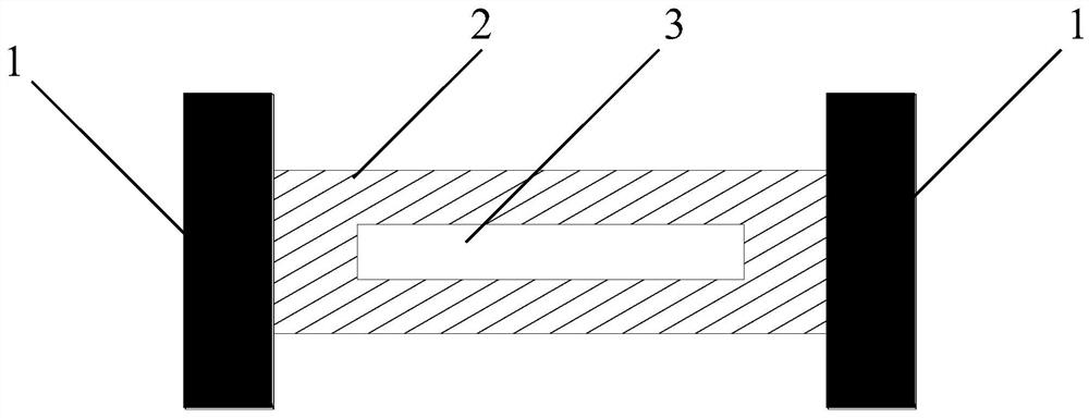
[0023] Such as figure 1 As shown, the photodetector structure based on perovskite nanowires includes an electrode 1, a perovskite nanowire 2, a silicon dioxide layer 5, and a silicon substrate layer 6. The silicon dioxide layer 5 is placed on the silicon substrate layer 6, and the perovskite The perovskite nanowire 2 is placed on the silicon dioxide layer 5, and the two ends of the perovskite nanowire 2 are respectively connected with two identical electrodes 1. Specifically, in this embodiment, the perovskite nanowire 2 is MAPbI 3 Nanowires, the width of which is between 0.5 microns and 2 microns. Such as figure 1 As shown, the perovskite nanowire 2 has a gap 3 . The slit 3 is strip-shaped along the length direction of the perovskite nanowire 2 . The strip-shaped gap 3 divides the perovskite nanowire 2 into two relatively thinner nanowires. The width of the two thinner nanowires is similar to the wavelength of the incident light, which is beneficial to enhance the interac...

Embodiment 2

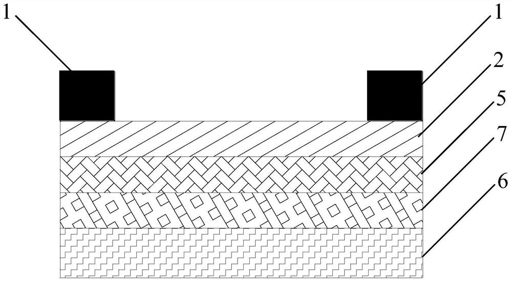
[0027] On the basis of Example 1, such as image 3 As shown, a metal film 7 is also provided between the silicon substrate layer 6 and the silicon dioxide layer 5 , and the perovskite nanowire 2 also has a gap 3 . In this way, the perovskite nanowire 2 forms a strong coupling with the metal thin film 7 and has surface plasmon resonance, which enhances the coupling between the perovskite nanowire 2 and incident light. Especially when the perovskite nanowire 2 has a slit 3 or a hole 4, a strong local electromagnetic field will be formed between the nanowire on both sides of the slit 3, the nanowire and the metal film 7, especially the nanowire and the metal film 7. The local electromagnetic fields between them are also distributed between the gaps 3, and these strong local electromagnetic fields are conducive to enhancing the coupling between the perovskite nanowires 2 and the incident light, thereby improving the detection sensitivity.

Embodiment 3

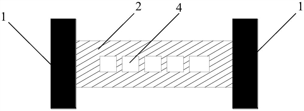
[0029] On the basis of Example 2, such as Figure 4 As shown, the metal thin film 7 is composed of no less than two strip structures 8 arranged in parallel. The arrangement direction of the strip structures 8 is perpendicular to the perovskite nanowires 2 . When the incident light is irradiated on the strip structure 8, a surface electromagnetic wave is formed on the strip structure 8, and the surface electromagnetic wave propagates along the strip structure 8. When the surface electromagnetic wave propagates to the below of the perovskite nanowire 2, the Coupled to the perovskite nanowire 2. Since these surface electromagnetic waves are excited at the non-perovskite nanowires 2, it is equivalent to increasing the area of ​​the perovskite nanowires 2 to receive incident light, thereby increasing the intensity of received light, and further improving detection sensitivity.


PUM

PropertyMeasurementUnit
widthaaaaaaaaaa

Abstract

The invention relates to the technical field of photodetection structures, in particular to a photodetection structure based on perovskite nanowires, including electrodes, perovskite nanowires with gaps, a silicon dioxide layer, and a silicon substrate layer. A silicon dioxide layer is placed on a silicon substrate layer, a perovskite nanowire with a gap is placed on the silicon dioxide layer, and electrodes are loaded on both ends of the perovskite nanowire with a gap. The perovskite nanowires with gaps can enhance the light absorption and reduce the cross-sectional area of ​​the current, thereby improving the detection sensitivity.

Description

technical field [0001] The invention belongs to the technical field of photodetection structures, and in particular relates to a photodetection structure based on perovskite nanowires. Background technique [0002] Perovskite materials are direct bandgap materials with broad absorption spectra from visible light to near-infrared waveguide, laying the foundation for their high photoelectric conversion efficiency. Although perovskite single crystals have extremely low density of defect states and have great application potential in realizing low-light detection, the sensitivity for low-light detection is still low. Contents of the invention [0003] In order to solve the above problems in the prior art, the present invention provides a light detection structure based on perovskite nanowires. The technical problem to be solved in the present invention is realized through the following technical solutions: [0004] A light detection structure based on perovskite nanowires, i...

Claims


Application Information

Patent Timeline
Patent Type & Authority Patents(China)
IPC IPC(8): H01L51/42H01L51/44
CPCH10K30/00H10K30/87Y02E10/549
Inventor 刘黎明余雪萍迟锋张智易子川刘萍杨健君水玲玲
Owner UNIV OF ELECTRONICS SCI & TECH OF CHINA ZHONGSHAN INST
Why Eureka
Try Eureka