
Method and apparatus for spinal distraction and fusion

Inactive Publication Date: 2005-11-24
MIS IP HLDG LLC
View PDF99 Cites 216 Cited by
  • Summary
  • Abstract
  • Description
  • Claims
  • Application Information

AI Technical Summary

Benefits of technology

[0046] There is provided in accordance with one aspect of the present invention, an apparatus for distracting and fusing two or more vertebral bodies. The apparatus is an implantable distraction / fusion rod that can be used to position and fixate vertebral bodies in the human spine. This rod would typically be used to facilitate fusion by means of bone bridging the motion segment within which the rod is inserted. The rod can serve many purposes, including but not limited to, modifying the gap between the bodies, assuming physiological axial loads, providing access for the introduction of osteogenic and / or osteoconductive materials.
[0051] The method additionally comprises the step of engaging a proximal end of the distraction device with respect to the first vertebral body and engaging a distal end of the distraction device with respect to the second vertebral body. The distraction device may then be manipulated, to increase the distance between the first and second vertebral bodies.
[0055] In accordance with a further aspect of the present invention, there is provided a method of increasing the distance between a first vertebral body and a second vertebral body. The method comprises the steps of providing an internal distraction device, having an elongate body, a first threaded surface on a proximal portion of the body and a second threaded surface on a distal portion of the body. The first threaded surface is engaged with the first vertebral body, and the second threaded surface is engaged with the second vertebral body. The distraction device may thereafter be rotated, to increase the distance between the first vertebral body and the second vertebral body.

Problems solved by technology

A number of spinal disorders are caused by traumatic spinal injuries, disease processes, aging processes, and congenital abnormalities that cause pain, reduce the flexibility of the spine, decrease the load bearing capability of the spine, shorten the length of the spine, and / or distort the normal curvature of the spine.
In addition, the annulus tends to thicken, desiccate, and become more rigid, lessening its ability to elastically deform under load and making it susceptible to fracturing or fissuring.
The fissure itself may be the sole morphological change, above and beyond generalized degenerative changes in the connective tissue of the disc, and disc fissures can nevertheless be painful and debilitating.
Nevertheless, even a contained disc herniation is problematic because the outward protrusion can press on the spinal cord or on spinal nerves causing sciatica.
Another disc problem occurs when the disc bulges outward circumferentially in all directions and not just in one location.
Mechanical stiffness of the joint is reduced and the spinal motion segment may become unstable shortening the spinal cord segment.
As the disc “roll” extends beyond the normal circumference, the disc height may be compromised, and foramina with nerve roots are compressed causing pain.
Patients who suffer from such conditions can experience moderate to severe distortion of the thoracic skeletal structure, diminished ability to bear loads, loss of mobility, extreme and debilitating pain, and oftentimes suffer neurologic deficit in nerve function.
Controversy exists regarding the preferred method of performing these fusions for various conditions of the spine.
Although these procedures are less invasive than open surgery, they nevertheless suffer the possibility of injury to the nerve root and dural sac, perineural scar formation, reherniation of the site of the surgery, and instability due to excess bone removal.
This procedure has many complications including severe pain and spasm, which may last up to several weeks following injection.
Although damaged discs and vertebral bodies can be identified with sophisticated diagnostic imaging, the surgical procedures are so extensive that clinical outcomes are not consistently satisfactory.
Furthermore, patients undergoing such fusion surgery experience significant complications and uncomfortable, prolonged convalescence.
Surgical complications include disc space infection, nerve root injury, hematoma formation, and instability of adjacent vertebrae.
As a result, the spinal column can be further weakened and / or result in surgery induced pain syndromes.
Only a limited access to and alignment of S1 and L5 can be achieved by this approach because the distal ends of the straight bore and shaft approach and threaten to perforate the anterior surface of the L5 vertebral body.
Thus, disadvantages to the present implants and surgical implantation techniques remain concerning the implantation procedures and involving post-surgical failure necessitating re-operation.
The exposed ends of the cage or side by side installed cages can irritate nerves causing pain to emerge again.
The large laterally drilled hole or holes can compromise the integrity of the vertebral bodies, and the spinal cord can be injured if they are drilled too posteriorly.
The endplates of the vertebral bodies, which comprise very hard cortical bone and help to give the vertebral bodies needed strength, are usually weakened or destroyed during the drilling.
The cylindrical cage or cages are now harder than the remaining bone of the vertebral bodies, and the vertebral bodies tend to collapse or “telescope” together.
The telescoping causes the length of the vertebral column to shorten and can cause damage to the nerve root and nerves that pass between the two adjacent vertebrae.
Since the pedicles of vertebrae above the second lumbar vertebra (L2) are very small, only small bone screws can be used which sometimes do not give the needed support to stabilize the spine.
These rods and screws and clamps or wires are surgically fixed to the spine from a posterior approach, and the procedure is difficult.
These approaches are criticized as failing to provide adequate medial-lateral and rotational support in the 899 patent.
These approaches involve considerable damage to ligaments and tissue in the anterior access to the vertebral bones.
The use of radiopaque metal cages or other metal implants also makes it difficult to image the disc space with radiographic imaging equipment to assess the degree of fusion achieved by bone growth between the vertebral bodies separated by the cages.
The filling of the bag under pressure tends to distract, i.e., to separate, the adjoining vertebral bodies to the physiologic separation that would be provided by the undamaged disc.
The posterolateral or anterior lateral approach is necessitated to correct the severe spondylolisthesis displacement using the reduction tool and results in tissue injury.
Vertebral compression fractures of healthy vertebral bodies can also occur due to injury.
In severe cases, the vertebral body tends to collapse, shortening the vertebral body and the spine and inducing an aberrant localized spinal curvature.
In most cases, the corset is not worn because the patient suffers much discomfort and oftentimes greater discomfort than that due to the fracture of the vertebral body.
The sheath or guide is advanced through the bore as the bore is made, making it not possible for the user to adjust the curvature of the bore to track physiologic features of the bone that it traverses.

Method used


Image

  • Method and apparatus for spinal distraction and fusion
  • Method and apparatus for spinal distraction and fusion
  • Method and apparatus for spinal distraction and fusion

Examples


Embodiment Construction

[0089] The methods and surgical instrumentation and axial spinal implants disclosed in co-pending, commonly assigned, related patent applications U.S. patent application Ser. No. 09 / 640,222 filed Aug. 16, 2000, U.S. patent application Ser. No. 09 / 684,820 filed Oct. 10, 2000, U.S. patent application Ser. No. 09 / 710,369 filed Nov. 10, 2000, U.S. patent application Ser. No. 09 / 709,105 filed Nov. 10, 2000, U.S. patent application Ser. No. 09 / 782,583 filed Feb. 13, 2001, U.S. patent application Ser. No. 09 / 848,556 filed May 3, 2001, U.S. patent application Ser. No. 10 / 125,771 filed Apr. 18, 2002, U.S. patent application Ser. No. 09 / 782,534 filed Feb. 13, 2001 can be employed in the practice of the present invention, and the disclosures of the above-identified applications are hereby incorporated in their entireties herein by reference.

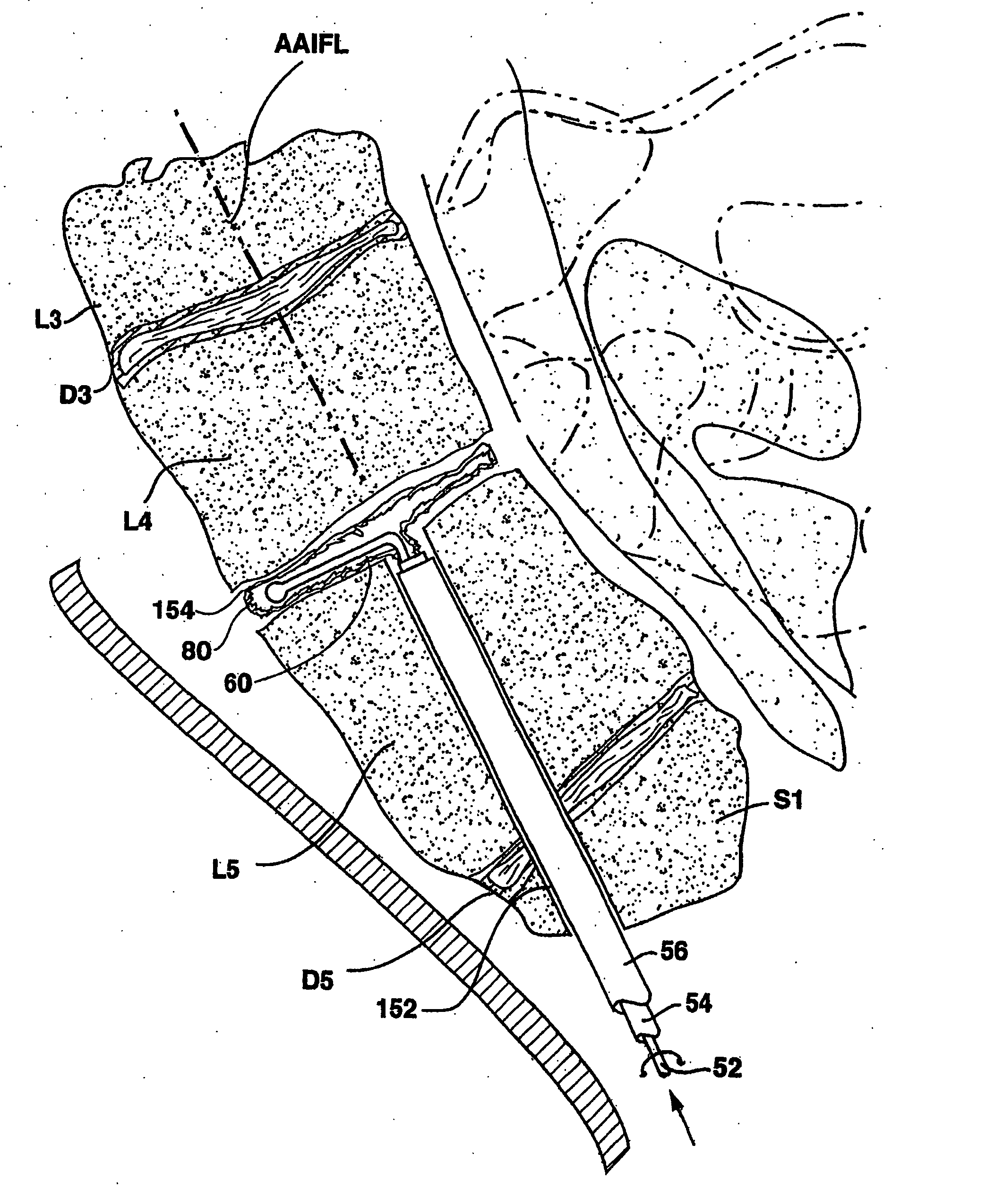
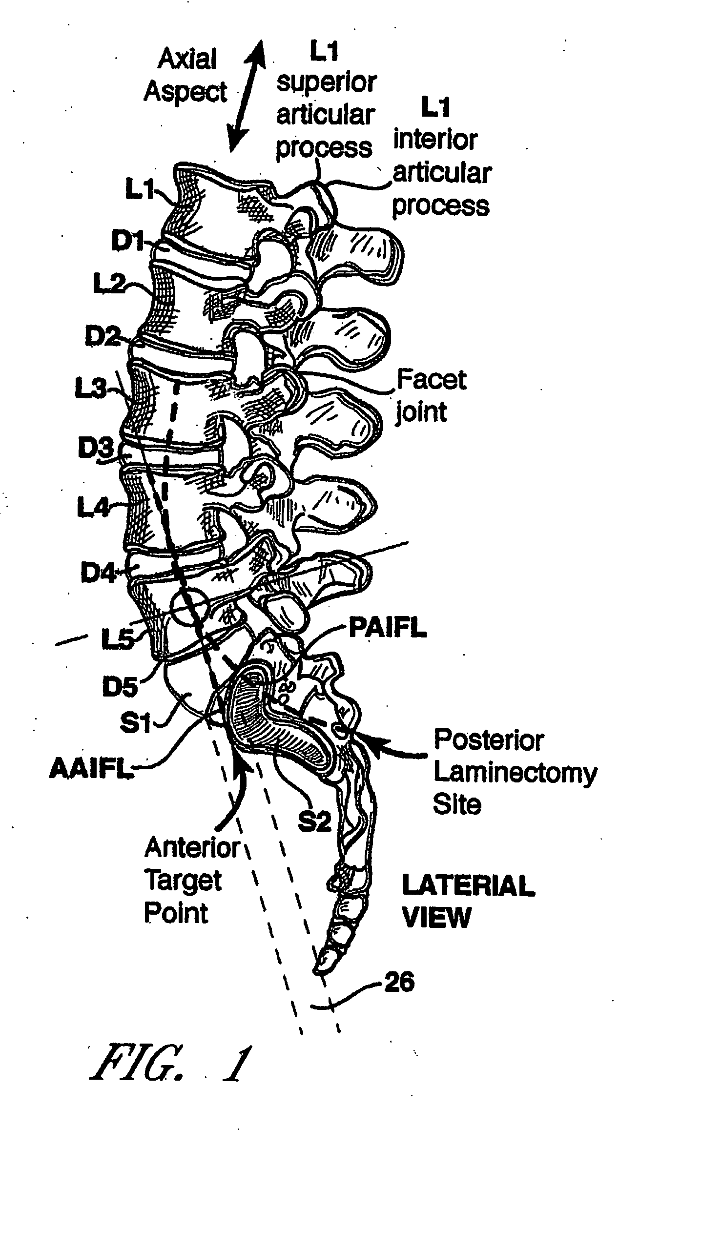
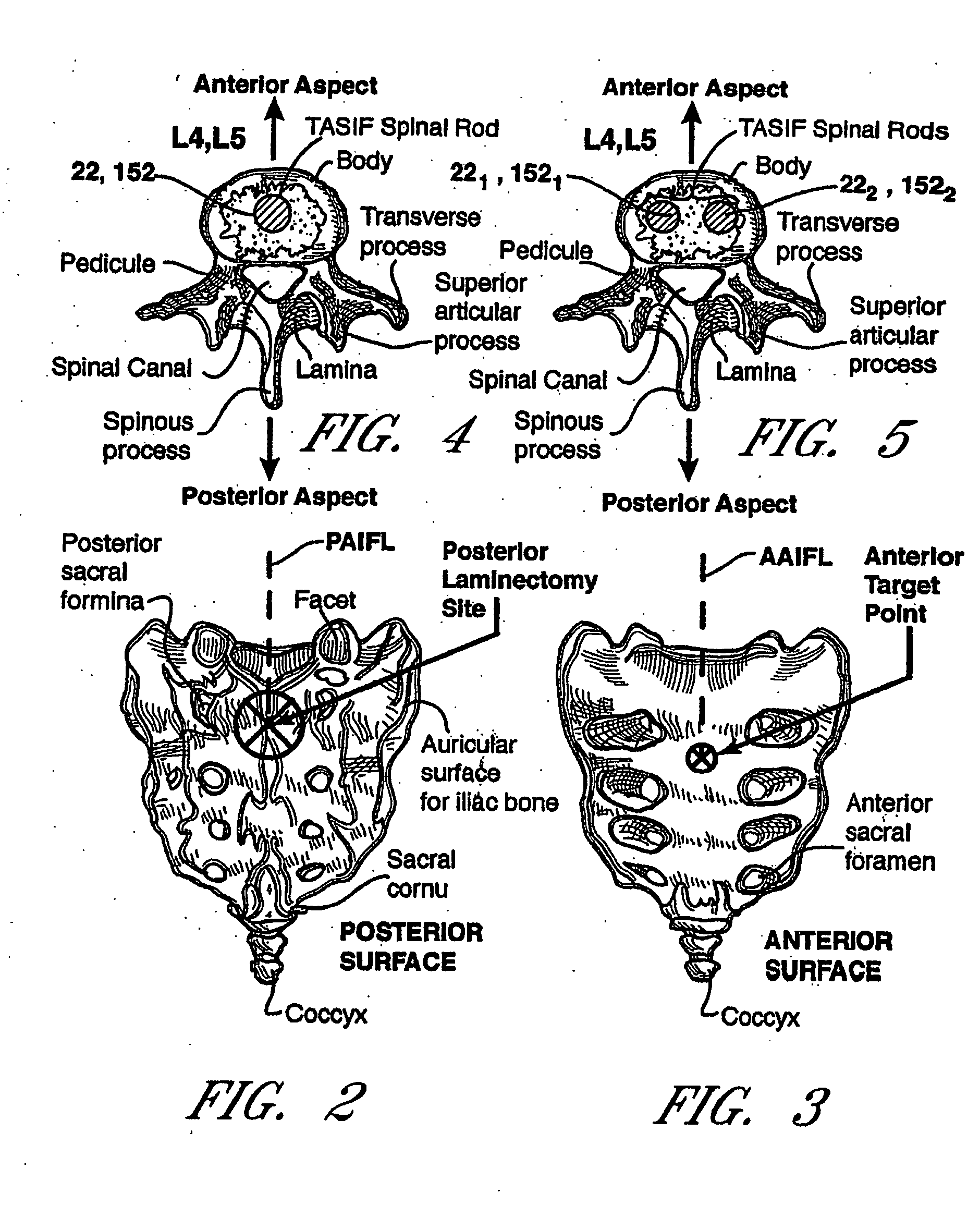
[0090]FIGS. 1-3 schematically illustrate the anterior and posterior TASIF surgical approaches in relation to the lumbar region of the spinal column, and F...


PUM

PropertyMeasurementUnit
Distanceaaaaaaaaaa

Abstract

The invention provides an implantable spinal distraction / fusion rod with varied thread pitch and diameters along different portions of its length that it is capable of distracting two or more vertebral bodies relative to each other and / or facilitating the procedure of fusing the vertebral bodies together from within the spine. The present invention also provides for methods of using the rod to distract and / or fuse two or more vertebral bodies from within the spine.

Description

[0001] This application is a continuation of U.S. patent application Ser. No. 10 / 309,416 filed on Dec. 3, 2002, which is a continuation-in-part of U.S. patent application Ser. No. 10 / 125,771 filed on Apr. 18, 2002, now U.S. Pat. No. 6,899,716 which is a continuation-in-part of U.S. patent application Ser. No. 09 / 848,556 filed on May 3, 2001 which is a continuation-in-part of U.S. patent application Ser. No. 09 / 782,583 filed on Feb. 13, 2001, now U.S. Pat. No. 6,558,390 which claims priority to U.S. Provisional Patent Application Ser. No. 60 / 182,748 filed on Feb. 16, 2000 the contents of each of which are incorporated in their entirety into this disclosure by reference.BACKGROUND OF THE INVENTION [0002] The present invention relates generally to spinal surgery, particularly methods and apparatus for forming one or more trans-sacral axial spinal instrumentation / fusion (TASIF) axial bore through vertebral bodies in general alignment with a visualized, trans-sacral anterior or posterior...

Claims


Application Information

Patent Timeline
IPC IPC(8): A61BA61B17/00A61B17/16A61B17/17A61B17/22A61B17/28A61B17/32A61B17/56A61B17/66A61B17/70A61B17/88A61F2/00A61F2/28A61F2/30A61F2/44A61F2/46A61F5/00
CPCA61B17/1671A61F2310/00976A61B17/32002A61B17/320725A61B17/66A61B17/70A61B17/7055A61B17/7061A61B17/8811A61B2017/00004A61B2017/00261A61B2017/00557A61B2017/00734A61B2017/00867A61B2017/2905A61B2017/320012A61B2017/320733A61B2017/564A61F2/30723A61F2/441A61F2/442A61F2/4455A61F2/4465A61F2/4601A61F2/4611A61F2002/2817A61F2002/2835A61F2002/30092A61F2002/30233A61F2002/30235A61F2002/3055A61F2002/30563A61F2002/30593A61F2002/30677A61F2002/30774A61F2002/30784A61F2002/3085A61F2002/30859A61F2002/30879A61F2002/4475A61F2002/448A61F2210/0014A61F2230/0069A61F2310/00023A61F2310/00796A61B17/1757
Inventor CRAGG, ANDREW H.ASSELL, ROBERT L.DICKHUDT, EUGENE A.
Owner MIS IP HLDG LLC
Learn More