Capacitor and method of manufacturing capacitor

Active Publication Date: 2017-05-04
NIPPON CHIMI CON CORP
View PDF7 Cites 0 Cited by
  • Summary
  • Abstract
  • Description
  • Claims
  • Application Information

AI Technical Summary

Benefits of technology

[0030]According to the present disclosure, since the impregnation path for the electrolyte solution to the additive layer of the separator is ensured, an ESR increase of the electrolytic capacitor is suppres

Problems solved by technology

When, however, polyvinyl-alcohol is added to the electrolyte solution, the viscosity of the electrolyte capacitor increases, and thus the impregnation performance of the electrolyte solution to t

Method used


Image

  • Capacitor and method of manufacturing capacitor
  • Capacitor and method of manufacturing capacitor
  • Capacitor and method of manufacturing capacitor

Examples


first embodiment

[0037](Structure)

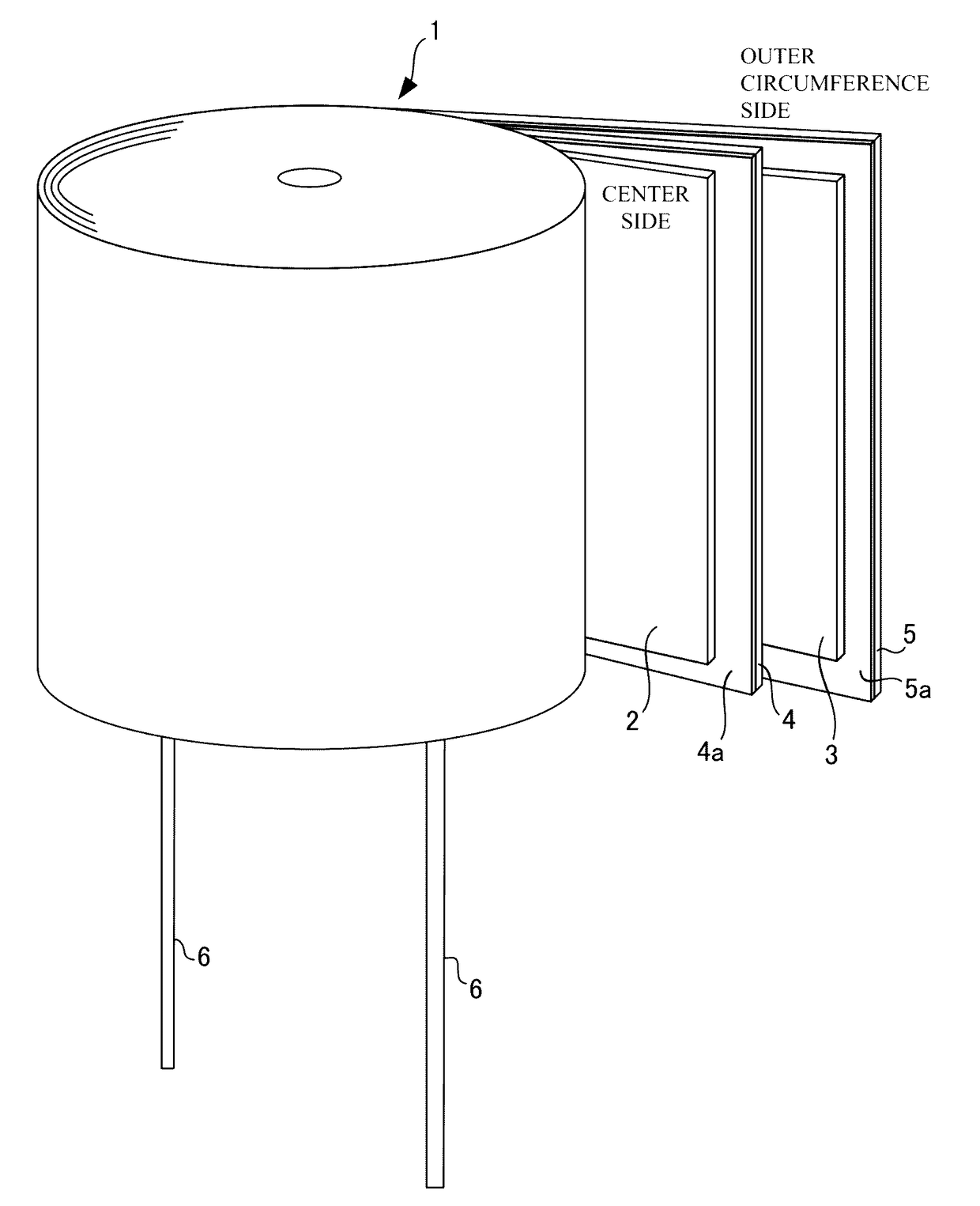
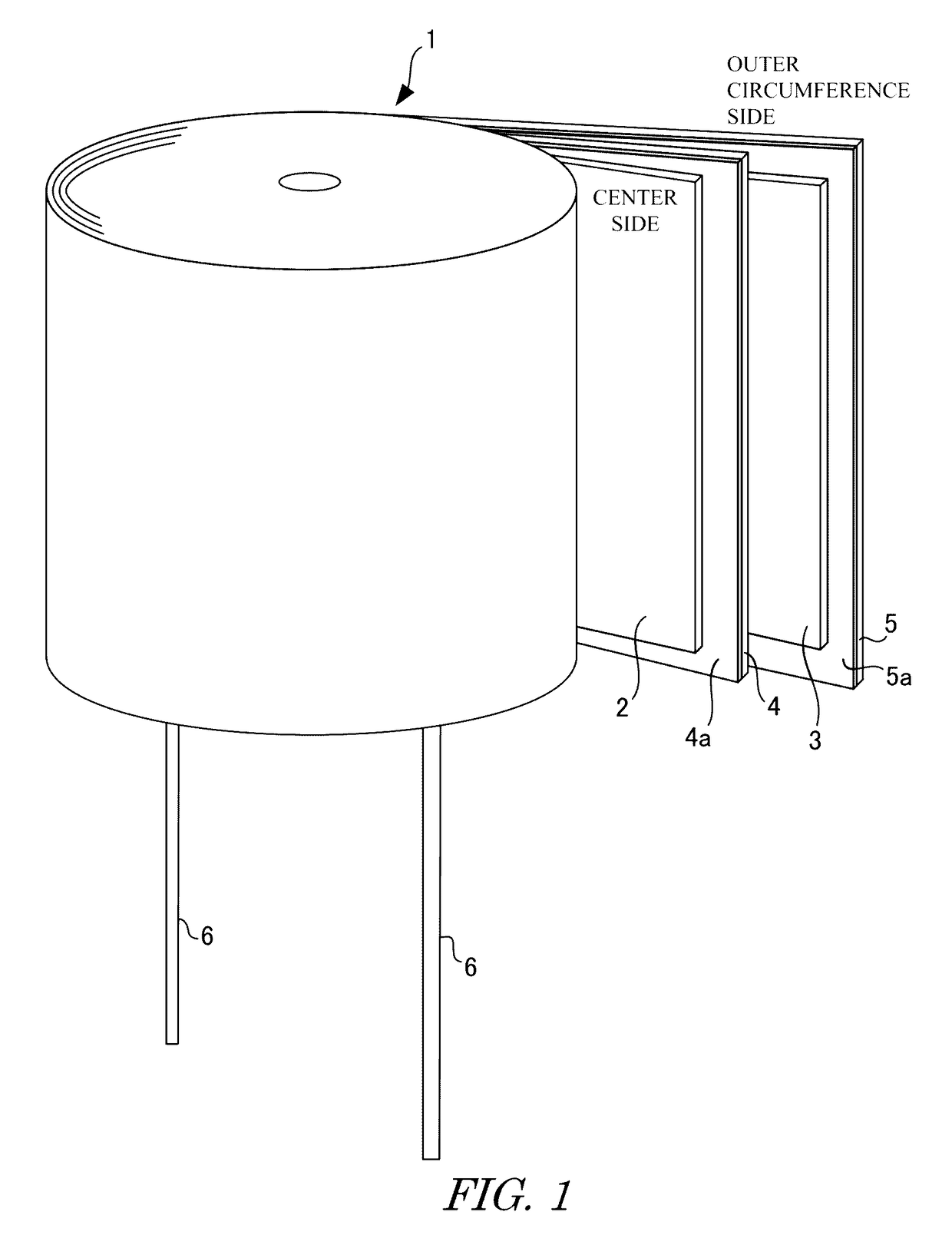
[0038]A structure of an electrolytic capacitor according to a first embodiment will be explained in detail with reference to FIGS. 1 and 2. The electrolytic capacitor is manufactured by impregnating a capacitor element 1 illustrated in FIG. 1 with an electrolyte solution, placing the capacitor element 1 into an outer casing, sealing the outer casing by a seal body, and finally performing a chemical re-conversion process.

[0039]As illustrated in FIG. 1, this capacitor element 1 is manufactured by connecting lead terminals 6, 6 to an anode foil 2 and a cathode foil 3 respectively, laminating the anode foil 2 and the cathode foil 3 with each other via a separator 4 and a separator 5 therebetween, and winding this laminated sheet.

[0040]A method for winding this laminated sheet is not limited to any particular scheme, but it is desirable that the cathode foil 3 to disposed at the outer circumference side in view of the improvement of a heat dissipation performance. For ex...

second embodiment

[0053](Structure)

[0054]The structure of an electrolytic capacitor according to a second embodiment will be explained in detail with reference to FIGS. 3 and 4. As illustrated in FIG. 3, each separators 4, 5 may be disposed in away that respective additive layers 4a, 5a may be disposed to face surfaces of the adjacent anode foil 2. That is, as for the separator 5, which is located adjacent to the anode foil 2 at the outer circumference side of the capacitor element 1 and located adjacent to the cathode foil 3 at the center side of the capacitor element 1, the additive layer 5a is also formed on not the surface facing the cathode foil 3 but on the surface facing the anode foil 2.

[0055](Action and Effect)

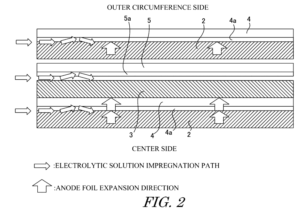
[0056]FIG. 4 shows a state in which the capacitor element 1 is impregnated with the electrolyte solution, and is a partial cross-sectional view illustrating cut along the orthogonal direction to the axial center. According to this capacitor element 1, the winding causes the additive la...

example

[0059]Examples according to the present disclosure will be explained in detail with reference to FIGS. 1 and 2. The anode foil 2 and the cathode foil 3 were laminated with each other via the separators 4, 5 having respective one surfaces adhered with polyvinyl-alcohol, and wound to produce the capacitor element 1. This capacitor element was impregnated with the electrolyte solution, placed in the outer casing, and this outer casing was sealed by a seal body. A chemical re-conversion process was applied, and the electrolytic capacitor was manufactured. As for the size of the capacitor, the diameter was 13.5 mm, and the entire length was 40 mm.

[0060]The capacitor element 1 according to this example has polyvinyl-alcohol layers 4a, 5a disposed on the respective surfaces of the separators 4, 5 at the center side of the capacitor element 1. That is, the separator 4, which is located adjacent to the anode foil 2 at the surface at the center side of the capacitor element 1 and is located a...


PUM


Abstract

An electrolytic capacitor accomplishing a suppression of an ESR rise and improvement of a productivity for electrolytic capacitors employing a manufacturing method of applying an additive layer to a separator beforehand prior to an impregnation of a capacitor element, and a manufacturing method of the same are provided. An anode foil 2 and a cathode foil 3 having undergone an area increasing process are laminated via separators 4, 5, on which additive layers 4a, 5a are formed on respective one surfaces, and wound to produce a capacitor element 1. At least the separator 4 facing the anode foil 2 via a surface at the center side of the capacitor element 1 and facing the cathode foil 3 at the outer circumference side has the additive layer 4a stuck on the surface at the center side. In addition, the produced capacitor element 1 having the additive layers 4a, 5a stuck on respective one surfaces of the separators 4, 5 and wound is impregnated with an electrolytic solution.

Description

TECHNICAL FIELD[0001]The present disclosure relates to a capacitor and a method of manufacturing the capacitor.BACKGROUND ART[0002]Electrolytic capacitors are passive elements that charge and discharge electrical charges by electrostatic capacity. Such electrolytic capacitors include a capacitor element impregnated with an electrolyte solution and placed in an outer casing, the outer casing is sealed by a seal body, and lead terminals are drawn out from the seal body. The capacitor element includes an anode foil formed of a valve metal foil such as aluminum with an oxide film as a dielectric layer formed thereof, a cathode foil formed of the same or different metal foil and facing the anode foil, and a separator between the anode foil and the cathode foil.[0003]The anode foil is produced by performing an area increasing process on a valve metal in order to increase the surface area, and then performing a chemical conversion process of applying a voltage in a chemical conversion solu...

Claims


Application Information

Patent Timeline
IPC IPC(8): H01G9/145H01G9/00H01G9/048H01G9/008H01G9/02
CPCH01G9/145H01G9/008H01G9/0029H01G9/048H01G9/02H01G9/035H01G9/055
Inventor ASHINO, HIROTSUGUSHIROTO, JUNYA
Owner NIPPON CHIMI CON CORP
Why Eureka
Try Eureka