Multilayer capacitor array

a capacitor array and multi-layer technology, applied in the direction of fixed capacitors, stacked capacitors, fixed capacitor details, etc., can solve the problems of increasing the number of laminated layers of dielectric layers, difficult to achieve a sufficient equivalent series resistance, and increasing the number of dielectric layers. , to achieve the effect of relieving stress concentration

Active Publication Date: 2009-08-13
TDK CORPARATION
View PDF23 Cites 1 Cited by
  • Summary
  • Abstract
  • Description
  • Claims
  • Application Information

AI Technical Summary

Benefits of technology

[0013]The multilayer capacitor array according to the present invention successfully achieves the high ESR while relieving the stress concentration due to electrostriction.

Problems solved by technology

This configuration has the problem that it is difficult to achieve a sufficient equivalent series resistance (which will be referred to hereinafter as ESR) of the multilayer capacitor array.
This problem becomes more prominent with increase in the number of laminated layers of the dielectric layers and internal electrodes for increasing the capacitance of the multilayer capacitor array.
For this reason, stress due to the electrostriction is concentrated in a portion without the internal electrodes between capacitor element portions, so that cracking or the like can occur there.

Method used


Image

  • Multilayer capacitor array
  • Multilayer capacitor array
  • Multilayer capacitor array

Examples


Embodiment Construction

[0025]The preferred embodiments of the multilayer capacitor array according to the present invention will be described below in detail with reference to the drawings.

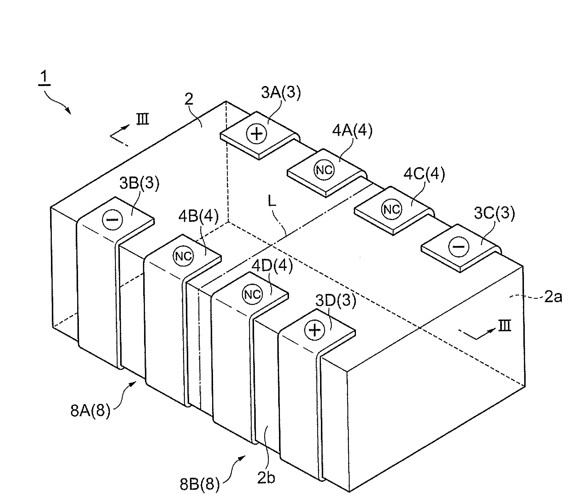
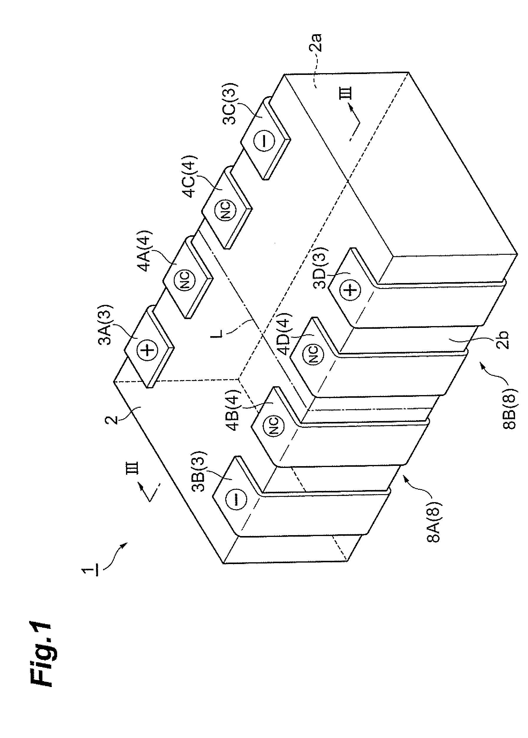
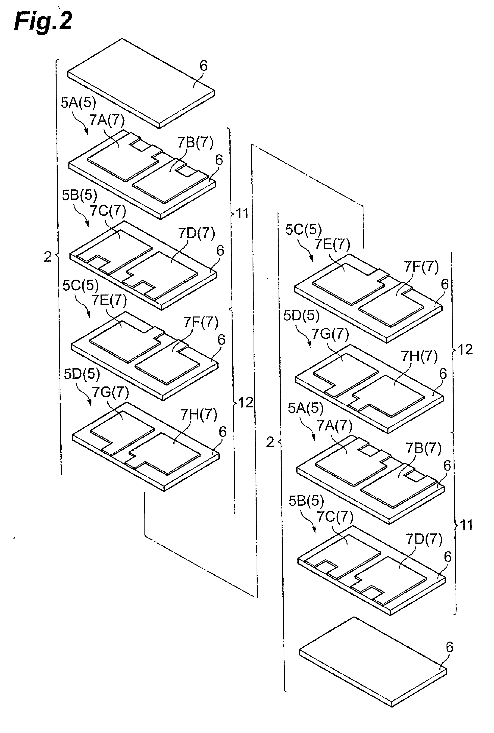
[0026]FIG. 1 is a perspective view showing an embodiment of the multilayer capacitor array according to the present invention. FIG. 2 is a drawing showing a layer configuration of the multilayer capacitor array shown in FIG. 1 and FIG. 3 a sectional view along line III-III in FIG. 1.

[0027]As shown in FIGS. 1 to 3, the multilayer capacitor array 1 has a laminate 2, and external electrodes 3 (3A-3D) and terminal conductors 4 (4A-4D) formed on side faces of the laminate.

[0028]The laminate 2, as shown in FIG. 2, is formed in a nearly rectangular parallelepiped shape as composed of a plurality of complex layers 5 in each of which internal electrodes 7 of different patterns are formed on a dielectric layer 6, and dielectric layers 6, 6 laminated together with the complex layer 5 in between and functioning as protecting layers...


PUM


Abstract

A multilayer capacitor array achieves a high ESR because terminal conductors to which internal electrodes in capacitance sections are connected in parallel are connected in series through internal electrodes in ESR control sections to external electrodes. Since in the multilayer capacitor array the internal electrodes extend as far as a boundary between capacitor element portions, electrostriction occurs in an entire laminate including a region near the boundary between the capacitor element portions, with application of a voltage from the outside. Therefore, concentration of stress due to electrostriction is avoided, so as to suppress occurrence of cracking or the like.

Description

BACKGROUND OF THE INVENTION[0001]1. Field of the Invention[0002]The present invention relates to a multilayer capacitor array.[0003]2. Relate Background Art[0004]A conventional multilayer capacitor array is, for example, the one described in Japanese Patent Application Laid-open No. 2000-331879. This conventional multilayer capacitor array is constructed in a structure in which dielectric layers and internal electrodes are alternately laminated together The multilayer capacitor array of this configuration is formed by applying an electroconductive paste to become the internal electrodes, onto ceramic greens to become the dielectric layers, so as to form separate patterns in a plurality of regions.SUMMARY OF THE INVENTION[0005]Incidentally, a commonly-used multilayer capacitor array has a structure in which all the internal electrodes are connected in parallel through a lead conductor to the corresponding external electrodes. This configuration has the problem that it is difficult to...

Claims


Application Information

Patent Timeline
Patent Type & Authority Applications(United States)
IPC IPC(8): H01G4/228
CPCH01G4/012H01G4/30H01G4/232A61F5/32A61F13/00A61F2013/00463A61F2013/00468
Inventor AOKI, TAKASHI
Owner TDK CORPARATION
Why Eureka
Try Eureka