Rolling bearing apparatus
a technology of rolling bearings and rolling bearings, which is applied in the direction of rolling bearings, mechanical devices, rigid supports of bearing units, etc., can solve the problems of wear of the roll neck part having a lower hardness, and achieve the effect of preventing creep and reducing stress concentration at the key groov
- Summary
- Abstract
- Description
- Claims
- Application Information
AI Technical Summary
Benefits of technology
Problems solved by technology
Method used
Image
Examples
first embodiment
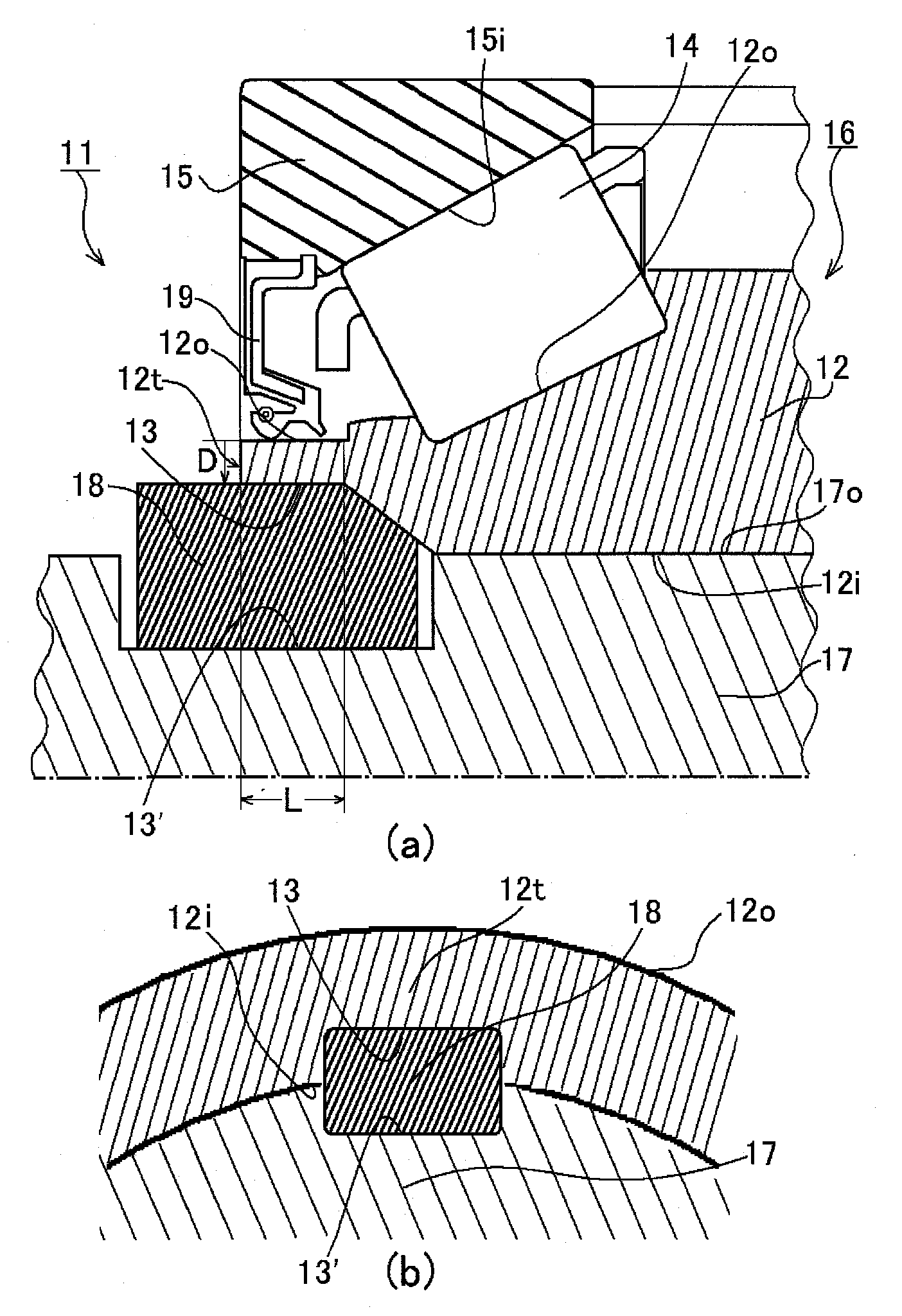
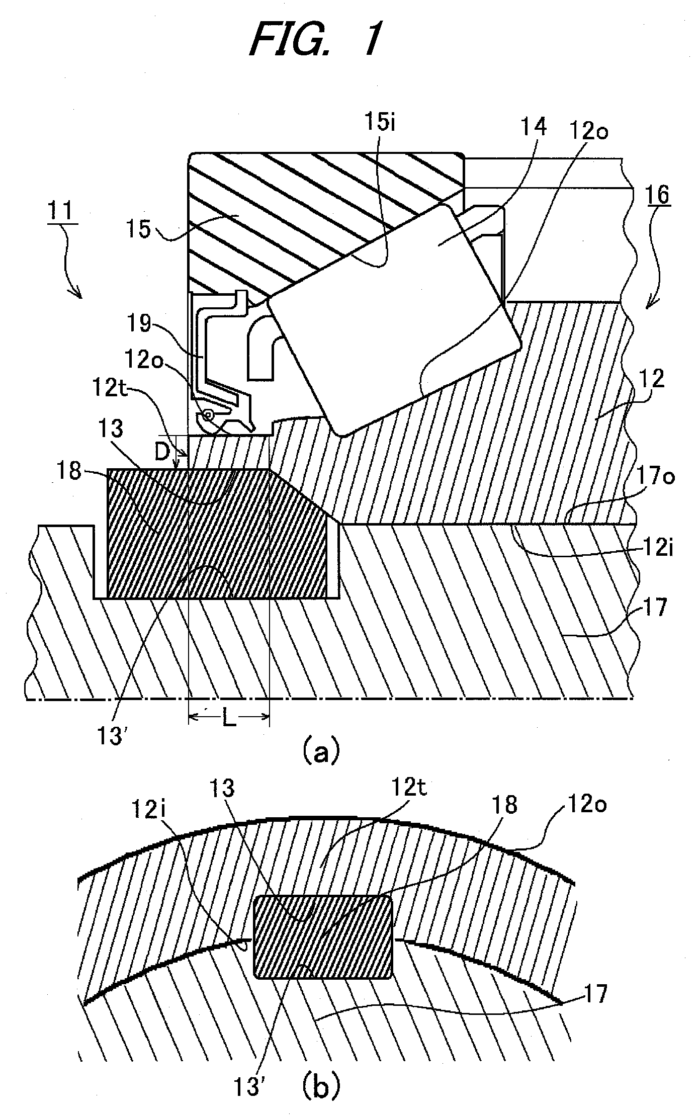
[0025]FIG. 1(a) is a vertical sectional view illustrating a main portion of a sealed rolling bearing apparatus 11 according to the first embodiment of the present invention, and FIG. 1(b) is a cross sectional view illustrating a key structure of the sealed rolling bearing apparatus 11 of FIG. 1(a).
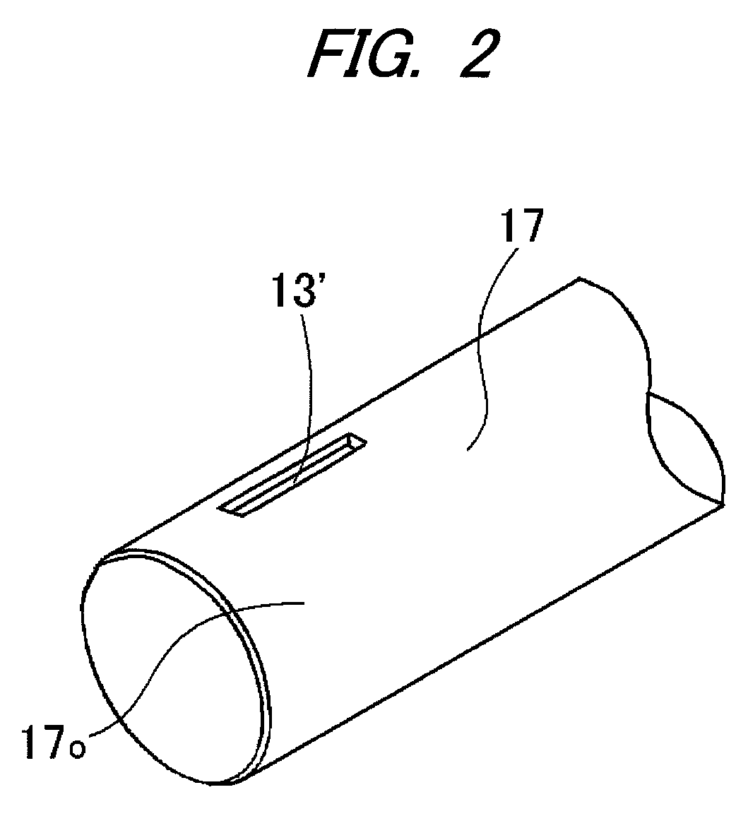
[0026]As shown in FIG. 1(a), the sealed rolling bearing apparatus 11 includes a rolling bearing 16 having an inner ring 12 provided with a first key groove 13 in its axial end portion 12t, a plurality of rolling elements 14 held on an outer peripheral face 12o of the inner ring 12 in a rollable manner, and an outer ring 15 provided with a raceway face for the rolling elements 14 on its inner peripheral face 15i. The sealed rolling bearing apparatus 11 further includes a rotation shaft 17, and a key 18. The rotation shaft 17 on which the rolling bearing 16 is incorporated is provided with a second key groove 13′ on its outer peripheral face 17o. The key 18 is inserted in a state in which th...
second embodiment
[0031]FIG. 3(a) is a vertical sectional view illustrating a main portion of a sealed rolling bearing apparatus 21 according to the second embodiment of the present invention, and FIG. 3(b) is a cross sectional view illustrating a key structure of the sealed rolling bearing apparatus 21 of FIG. 3(a). Those parts corresponding to the preceding drawings are denoted with the same reference numerals, and descriptions thereof will be omitted.
[0032]As shown in FIGS. 3(a) and 3(b), a first key groove 23 is provided in an axial end portion 22t of an inner ring 22 and is opened at an inner peripheral face 22i. The first key groove 23 is formed so as to have a predetermined length L in the axial direction from the axial end portion 22t of the inner ring 22 at a position having a certain depth D from an outer peripheral face 22o in a radial direction. The first key groove 23 has a substantially quadrangular cross section. A seal 19 for tight sealing is provided on an outer side of a rolling bea...
third embodiment
[0036]FIG. 4(a) is a vertical sectional view illustrating a main portion of a sealed rolling bearing apparatus 31 according to a third embodiment of the present invention, and FIG. 4(b) is a cross sectional view illustrating a key structure of the sealed rolling bearing apparatus of FIG. 3(a). Those parts corresponding to the preceding drawings are denoted with the same reference numerals and descriptions thereof will be omitted.
[0037]As shown in FIG. 4, a first key groove 33 is provided in an axial end portion 32t of an inner ring 32 and is opened at an inner peripheral face 32i. The first key groove 33 is formed so as to have a predetermined length L in the axial direction from the axial end portion 32t of the inner ring 32 at a position having a certain depth D from an outer peripheral face 32o in a radial direction. The first key groove 33 has a substantially semicircular cross section. A seal 19 for tight sealing is provided on an outer side of a rolling bearing 36 for the purp...
PUM
 Abstract
Description
Claims
Application Information
 - R&D
- Intellectual Property
- Life Sciences
- Materials
- Tech Scout
- Unparalleled Data Quality
- Higher Quality Content
- 60% Fewer Hallucinations
Browse by: Latest US Patents, China's latest patents, Technical Efficacy Thesaurus, Application Domain, Technology Topic, Popular Technical Reports.
© 2025 PatSnap. All rights reserved.Legal|Privacy policy|Modern Slavery Act Transparency Statement|Sitemap|About US| Contact US: help@patsnap.com


