

Bead foam molded member for vehicle seat and cushion member for vehicle seat
- Summary
- Abstract
- Description
- Claims
- Application Information
AI Technical Summary
Benefits of technology
Problems solved by technology
Method used
Image

Examples
Embodiment Construction
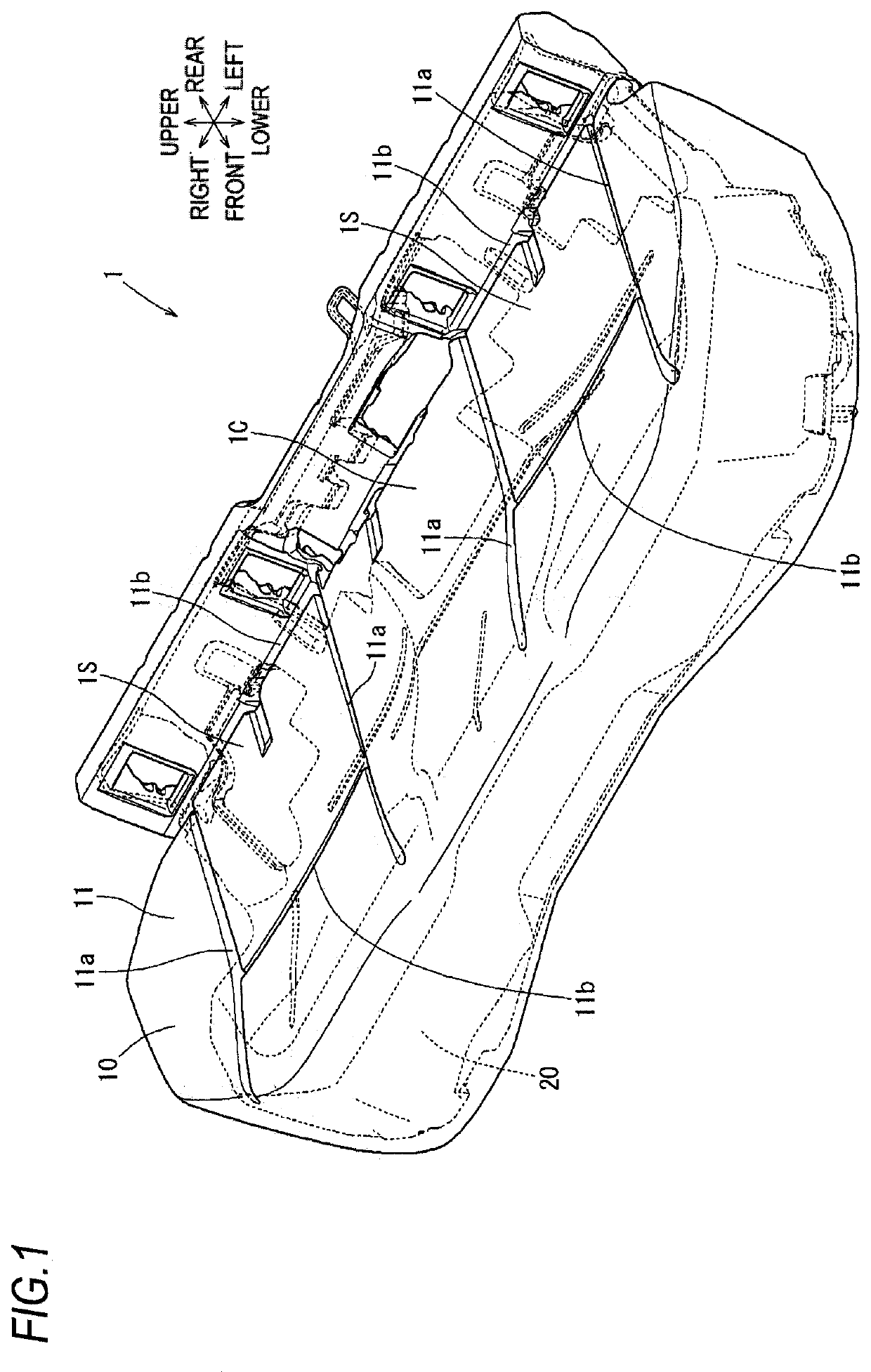
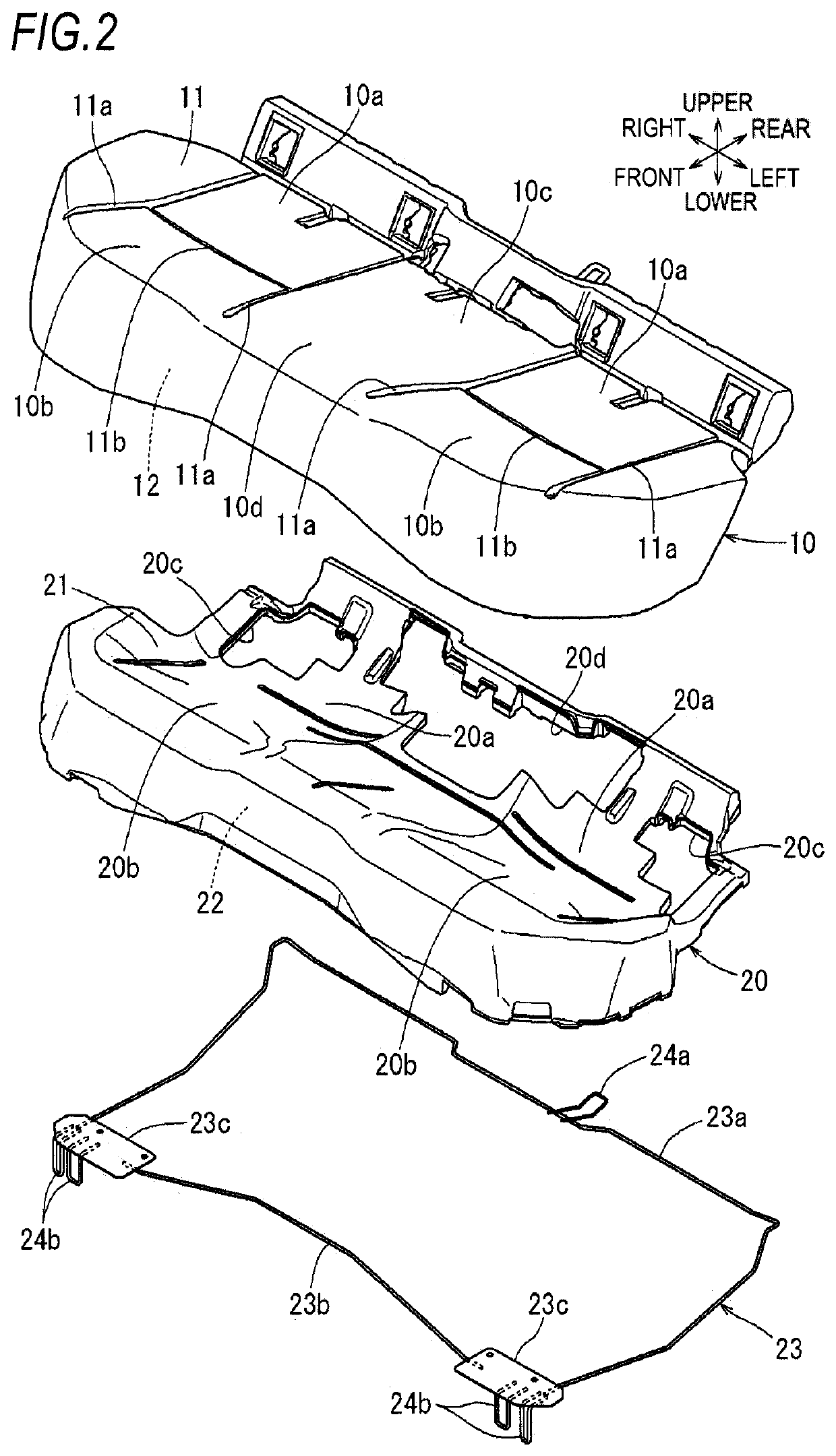
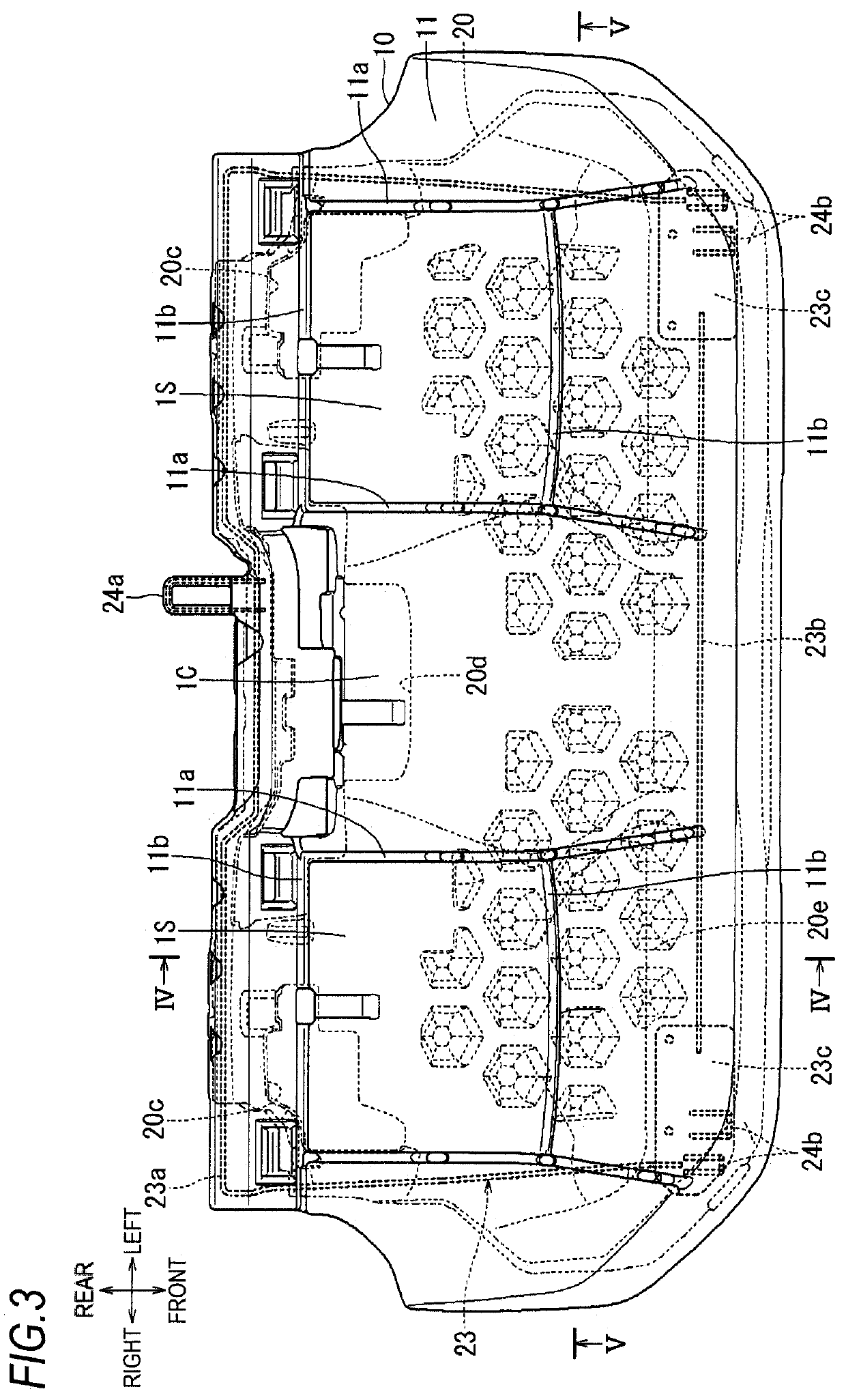
[0014]A bead foam molded member 20 according to an embodiment of the present disclosure will be described with reference to FIG. 1 to FIG. 5 together with a cushion pad 1 which is a cushion member of an automobile seat formed by integrating the bead foam molded member 20. In each figure, arrows indicate directions of the automobile and the cushion pad 1 when the cushion pad 1 is attached to a floor of the automobile. In the following description, directions will be described based on the directions defined above.
[0015]As shown in FIG. 1, the cushion pad 1 is for a seat cushion of a three-person bench seat, and has a length in a left-right direction substantially the same as a width of a vehicle cabin. A cushion cover (not shown) is covered on the cushion pad 1 to form the seat cushion. A rear seat is configured by combining a seat back (not shown) having a similar configuration as the seat cushion with the seat cushion in a state where the seat back is erected on a rear end portion ...
PUM
 Abstract
Description
Claims
Application Information