Screwdriver Bit

Inactive Publication Date: 2012-11-15
TOTSU KATSUYUKI
View PDF14 Cites 7 Cited by
  • Summary
  • Abstract
  • Description
  • Claims
  • Application Information

AI Technical Summary

Benefits of technology

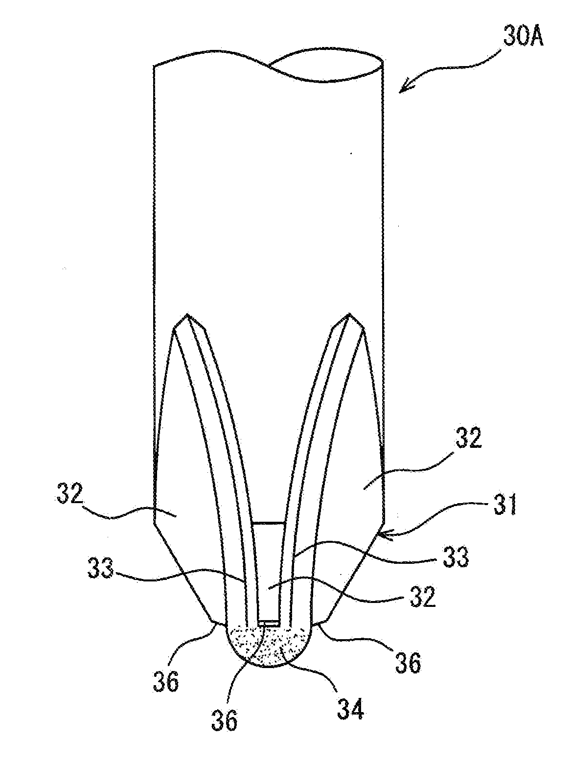
[0021]According to the screwdriver bit described in claim 1 of the present invention, when a tip end portion of the screwdriver bit is fitted to a bit fitting groove of a screw, an occurrence of a damage to a top surface of a screw head portion can be prevented, fitting of the bit tip end portion to the bit fitting groove can be achieved promptly and smoothly, and the efficiency and the safety of a screw fastening operation can considerably be promoted. That is, by forming the tip end face of the tip end bit portion of the screwdriver bit in the spherical shape by the mirror finish, when the tip end bit portion of the screwdriver bit is fitted to the bit fitting groove of the screw with a required acceleration, in a case where the tip end face is brought into contact with the top surface of the screw head portion, even when a positional shift between the bit and groove or a deviation of center axes of the bit and the screw or the like is brought about, not only an occurrence of a significant damage to the top surface of the screw head portion can be prevented, but proper and prompt fitting of the bit tip end portion to the bit fitting groove can smoothly be guid

Problems solved by technology

There is a difficulty that a proper screw fastening operation cannot be carried out.
Furthermore, in a case where the damage is

Method used


Image

  • Screwdriver Bit
  • Screwdriver Bit
  • Screwdriver Bit

Examples


Example

Example 1

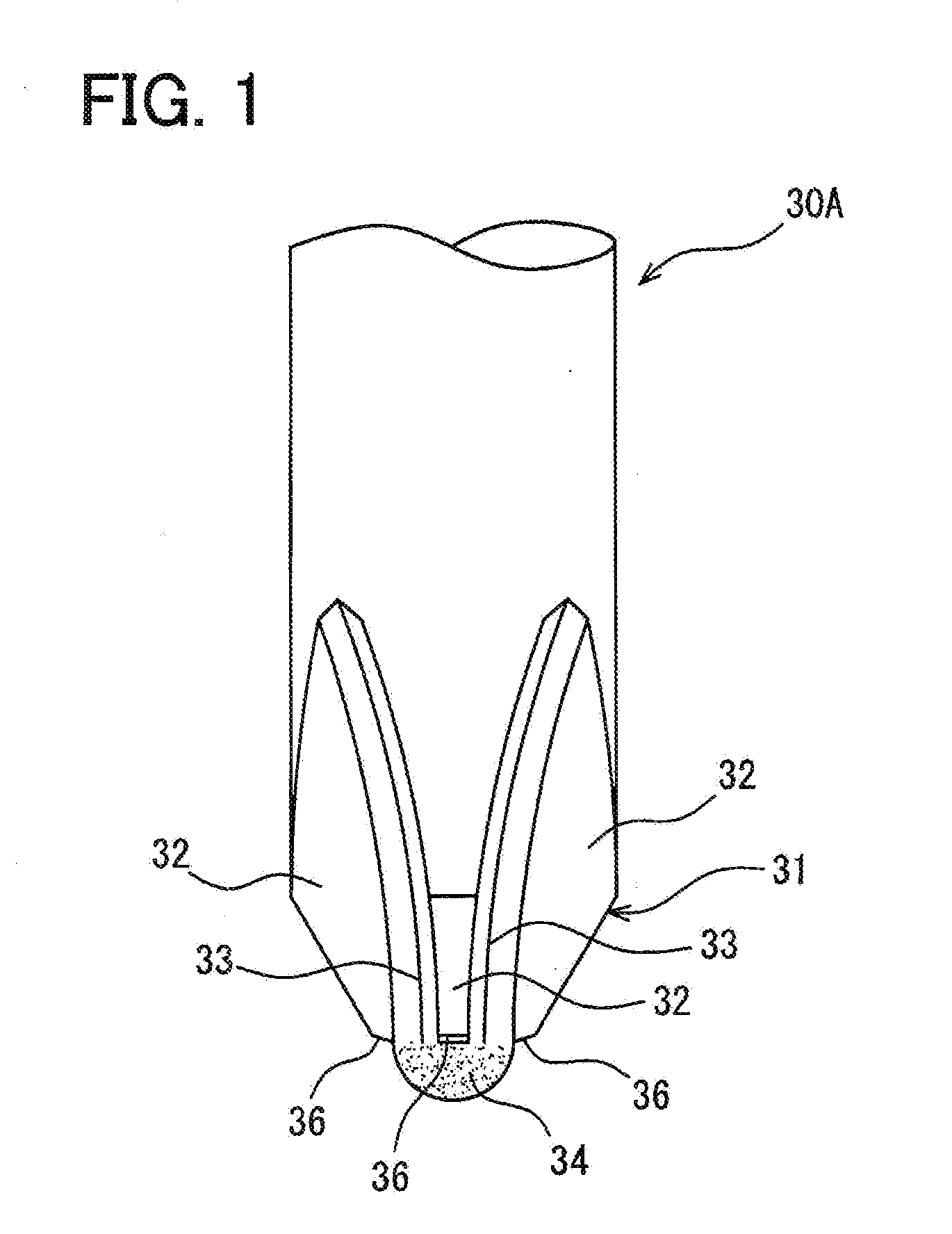
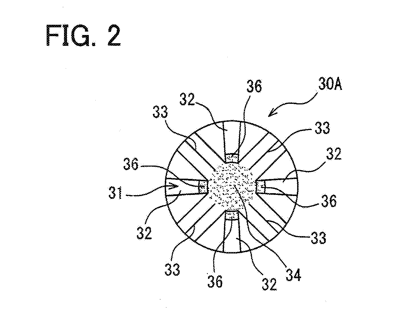
[0033]FIG. 1 and FIG. 2 show an example of a screwdriver bit according to the present invention, FIG. 1 is an outline side view of a tip end bit portion, and FIG. 2 is an outline end face view of a tip end face of the tip end bit portion. In FIG. 1 and FIG. 2, reference sign 30A designates a plus type screwdriver bit which includes a tip end bit portion 31 which is provided with a cross-shaped bit piece 32 that is fitted to a bit fitting groove of a screw consisting of a cross-shaped groove that is formed at a top surface of a screw head portion and which is protruded in a circular cone shape.

[0034]Nevertheless, the plus type driver bit 30A of the example that is configured in this way can be formed similar to the plus type driver bit 10 of the background art as shown in FIGS. 7a through 7c. That is, basically, the bit configuring material M in the rod-like shape is pertinently held by the chuck 2 of the machine tool [refer to FIG. 7a], and while rotating the bit configurin...

Example

Example 2

[0038]FIG. 4 and FIG. 5 show other embodiment of a screwdriver bit according to the present invention, FIG. 4 is an outline side view of a tip end bit portion, and FIG. 5 is an outline plan view of a tip end face of the tip end bit portion. Incidentally, for convenience of explanation, an explanation will be given by attaching the same reference sign to a constituent element the same as that of Example 1 shown in FIG. 1 through FIG. 3. Therefore, in FIG. 4 and FIG. 5, reference sign 30B designates a plus type screwdriver bit which includes the tip end bit portion 31 which is provided with the cross-shaped bit piece 32 that is fitted to a bit fitting groove of a screw consisting of a cross-shaped groove that is formed at a top surface of a screw head portion and which is protruded in a circular cone shape.

[0039]Nevertheless, also in the plus type driver bit 30B of the present example, quite similar to Example 1 described above, as shown in FIGS. 7a through 7c, the plus type ...


PUM


Abstract

A screwdriver bit configured in such a way that when the tip of the screwdriver bit is to be fitted into a bit fitting groove of a screw, said bit fitting groove being formed on the top surface of the head of the screw, then damage is prevented from occurring on the top surface of the head of the screw, and proper fitting of the tip of said bit into the bit fitting groove is promptly and smoothly accomplished, with the result that the efficiency and safety of screw tightening work are significantly enhanced. This driver bit (30) is provided with a cross-shaped tip edge which is to be fitted into the bit fitting groove provided on the top surface of the head of the screw, said bit fitting groove consisting of a cross-shaped groove. In this driver bit (30), the tip surface of said tip edge (31) is formed as a whole into a spherical surface shape (34) by means of planishing.

Description

TECHNICAL FIELD[0001]The present invention relates to a screwdriver bit which is configured such that in a screw fastening operation, when a tip end portion of the screwdriver bit is fitted to a bit fitting groove of a screw that is formed at a top surface of a screw head, a damage to a surrounding of the bit fitting groove at the top surface of the screw head can be prevented, fitting of the tip end portion of the bit to the bit fitting groove can be accomplished promptly and smoothly, and the efficiency and the safety of the screw fastening operation can considerably be promoted.BACKGROUND ART[0002]Generally, there is widely used a plus type screwdriver bit which consists of a configuration in which a cross-shaped bit portion is provided at a tip end portion so as to be adapted to a plus thread which is formed with a bit fitting groove that consists of a cross-shaped groove at a top surface of a screw head portion. Ordinarily, according to a plus type screwdriver bit of this kind,...

Claims


Application Information

Patent Timeline
IPC IPC(8): B25B15/00
CPCB25B15/005
Inventor TOTSU, KATSUYUKI
Owner TOTSU KATSUYUKI
Why Eureka
Try Eureka