
Solar panel mounting structure

a solar panel and mounting structure technology, applied in the direction of heat collector mounting/support, pv power plants, light and heating equipment, etc., can solve the problems of difficult inserting cleaning tools and the like, frequent entry and accumulation of gaps, damage to the roof, etc., to prevent damage or rain leaking in the roof, the effect of enhancing the cleaning workability of the roo

Inactive Publication Date: 2013-09-03
EIJYU SANGYO
View PDF10 Cites 8 Cited by
  • Summary
  • Abstract
  • Description
  • Claims
  • Application Information

AI Technical Summary

Benefits of technology

[0008]To solve the problems, it is an object of the present invention to provide a solar panel mounting structure which is excellent in cleaning workability and maintenance easiness after the construction.
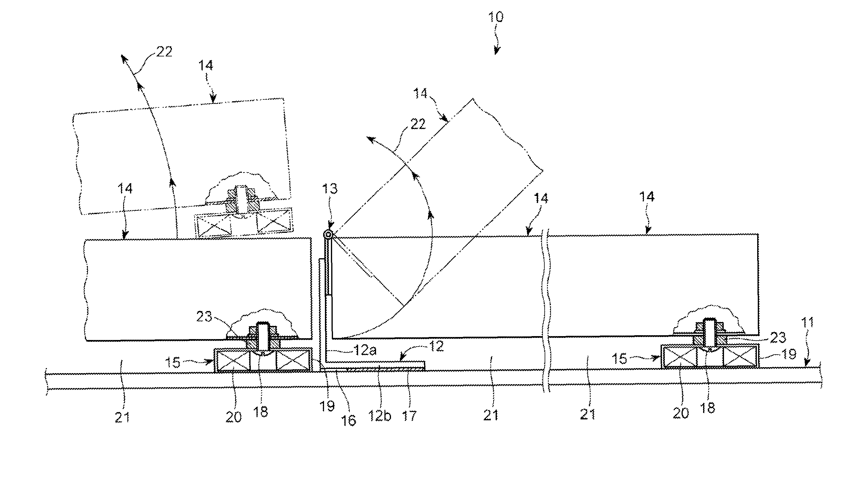
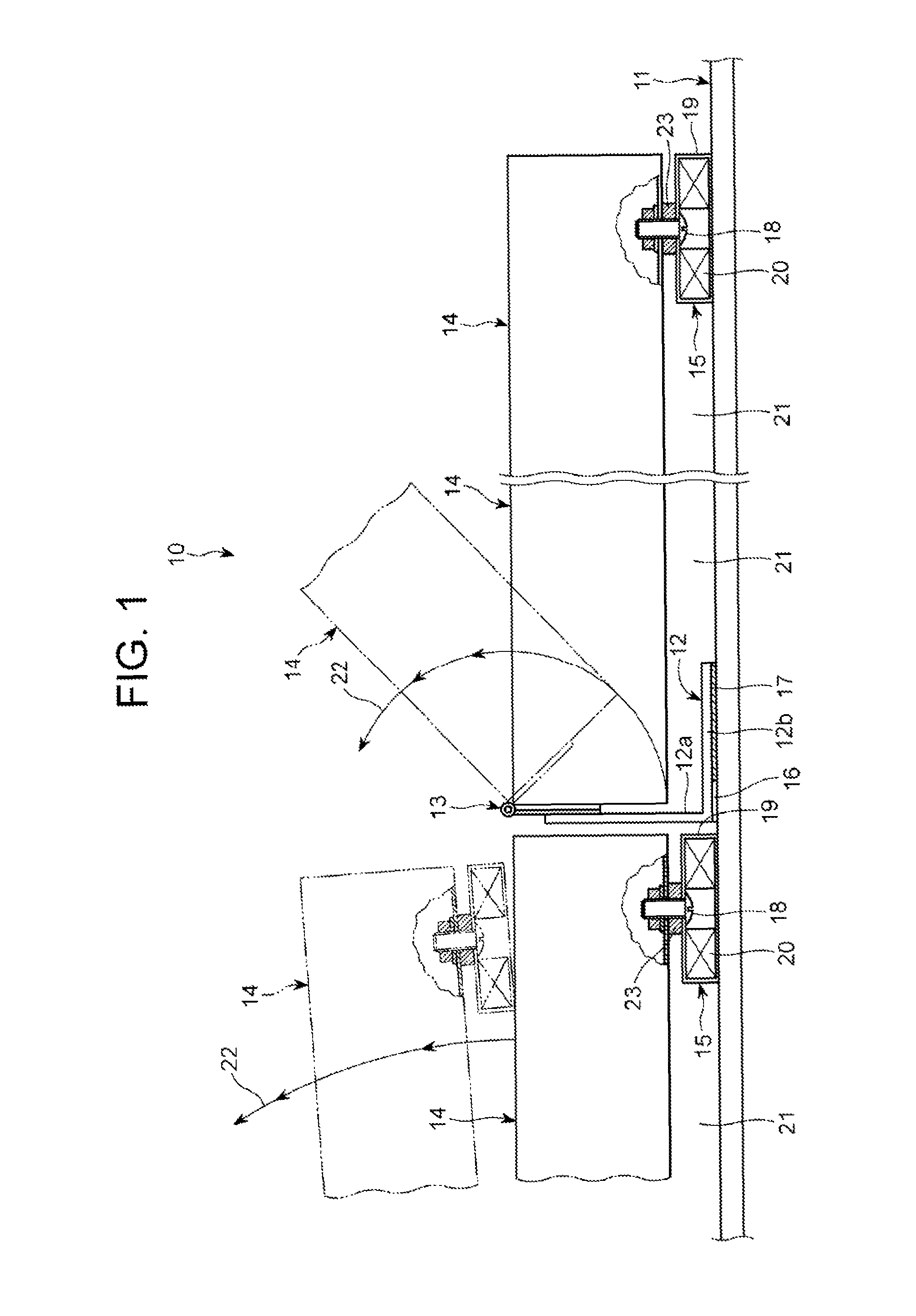
[0010]With such a configuration, the solar panel is held on the fixation member while interposing the hinge therebetween, and the fixation member is firmly fixed onto the roofing. Therefore, the fixation member becomes rotatable about the hinge even after the construction by releasing the magnetic engaging device. Accordingly, if the solar panel is rotated in an erection direction to thereby widen a gap between the solar panel and the roofing, and a state where the roofing is exposed is brought about, then cleaning, maintenance and the like of the roofing can be easily performed. Moreover, it becomes easy to remove leaves, dust and the like, which accumulate in the gap. Accordingly, by periodically performing the cleaning and the maintenance, an occurrence of damage or rain leaking in the roofing can be prevented.
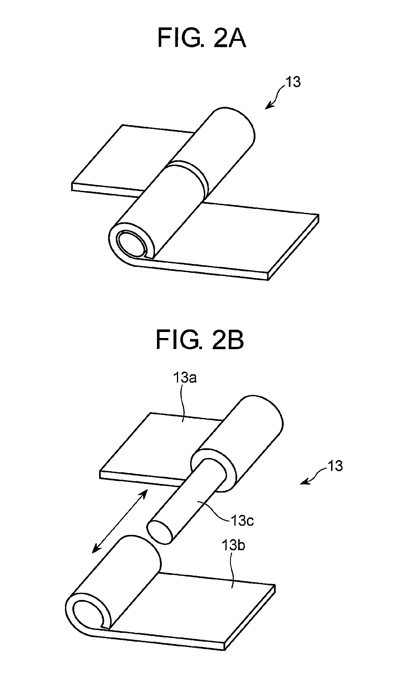
[0011]Here, if an insertion / extraction hinge is used as the hinge, then it becomes possible to remove the solar panel itself from the fixation member. Accordingly, not only cleaning workability for the roofing is enhanced, but it also becomes easy to perform the maintenance of the solar panel and replacement work with other solar panels.
[0012]Meanwhile, if at least one of an adhesive agent and a double-sided adhesive tape is used as a fixing device for fixing the fixation member to the roofing, then it becomes possible to firmly fix the fixation member to the roofing without using screws, nails and the like. Accordingly, mounting work of the solar panel becomes easy, and an effect is also brought in preventing leaks.
[0013]In accordance with the present invention, the solar panel mounting structure can have excellent cleaning workability and each maintenance after the construction.

Problems solved by technology

Accordingly, with an elapse of time after construction, leaves, dust and the like, which are carried by wind and rain, frequently enter and accumulate in the gap.
Leaves, dust and the like, which accumulate in the gap, damage roofing.
Accordingly, leaves, dust and the like not only deteriorate an exterior appearance of a building, but also corrode the roofing by maintaining a moisture-containing state, sometimes causing leaks.
However, the gap is narrow, and it is difficult to insert a cleaning tool and the like thereinto.
However, in the apparatus described in each of Patent Literatures 1 and 2, the solar panel is tightly fixed to the roof by screws and the like, and accordingly, it is difficult to detach the solar panel from the roof.

Method used


Image

  • Solar panel mounting structure
  • Solar panel mounting structure
  • Solar panel mounting structure

Examples


Embodiment Construction

[0016]As shown in FIG. 1, a solar panel mounting structure 10 of this embodiment includes: a fixation member 12 as an angle member, which has an L-shape in cross section, and which is firmly fixed to roofing 11 composed of a metal plate as a magnetic material; solar panels 14, each of which is rotatably held on the fixation member 12 while interposing an insertion / extraction hinge 13 mounted on an upper edge of an erected portion 12a of the fixation member 12; and a magnetic engaging device 15 provided between the solar panel 14 and the roofing 11 in order to detachably fix the solar panel 14 to the roofing 11.

[0017]As a device for firmly fixing the fixation member 12 to the roofing 11, a double-sided adhesive tape 16 and an adhesive agent 17 are interposed between a lower surface of a fixed portion 12b of the fixation member 12, which makes a right angle with the erected portion 12a thereof, and a surface of the roofing 11. The double-sided adhesive tape 16 functions as an initial ...


PUM


Abstract

A solar panel mounting structure includes: a fixation member as an angle member firmly fixed onto a roofing composed of a metal plate as a magnetic material; solar panels, each of which is rotatably held on the fixation member while interposing an insertion / extraction hinge mounted on an upper edge of an erected portion of the fixation member; and a magnetic engaging device provided between the solar panel and the roofing in order to detachably fix the solar panel to the roofing. The fixation member is firmly fixed to the roofing while interposing a double-sided adhesive tape and an adhesive agent therebetween. The magnetic engaging device includes: a cup-like casing mounted to a lower surface of the solar panel by a screw; and a ferrite magnet firmly fixed into the casing.

Description

BACKGROUND OF THE INVENTION[0001](1) Field of the Invention[0002]The present invention relates to a solar panel mounting structure for use at the time of installing a solar panel to a roof covered with a metal plate as a magnetic material.[0003](2) Description of Related Art[0004]With regard to a mounting structure for installing a solar panel to a roof covered with a metal plate, various patterns have been heretofore proposed. As a structure related to the invention of this application, for example, there is “an installation apparatus of equipment placed on the roof” described in Japanese Unexamined Patent Application Publication No. 2006-57397 as Patent Document 1 or “a solar panel mounting apparatus” described in Japanese Unexamined Patent Application Publication No. 2009-91811 as Patent Document 2. The apparatus described in each of Patent Documents 1 and 2 has a structure in which the solar panel is fixed to a support formed by assembling predetermined parts to fix them on the ...

Claims


Application Information

Patent Timeline
Patent Type & Authority Patents(United States)
IPC IPC(8): E04D13/18
CPCF24J2/5245Y02B10/12Y02B10/20Y02E10/47F24J2002/5486F24J2002/4676F28F2275/22F24S25/61F24S2025/601F24S2030/16Y02B10/10Y02E10/50
Inventor TACHINO, TAKASHI
Owner EIJYU SANGYO
Learn More