Flux-enhanced energy harvesting from current-carrying conductors

a current-carrying conductor and current-enhanced technology, which is applied in the direction of inductance, power distribution line transmission, transportation and packaging, etc., can solve the problems of short-term power sources, inability to provide the ongoing power required for most devices, and limited life of batteries, so as to increase the output voltage and power of the coil. , the effect of easy installation

Active Publication Date: 2018-02-15
RGT UNIV OF CALIFORNIA
View PDF0 Cites 7 Cited by
  • Summary
  • Abstract
  • Description
  • Claims
  • Application Information

AI Technical Summary

Benefits of technology

[0012]For these applications, the harvested electric power should be at least few milliwatts and the DC output voltage for battery charging should be about 5 volts. The technology described herein is relatively compact (volume of a few cubic centimeters), is easily installable, is inexpensive, and operates without creating audible noise. The technology also may be capable of functioning unattended for 10 years or more.
[0013]The apparatus is a coil-based with one or more very thin sheets of high magnetic permeability steel encasing the coil that help direct into the coils the time-varying magnetic flux produced by the AC current flowing in the conductor line. The steel sheets are flux concentrators that redirect the magnetic flux to interact more strongly with the coil, and so increase the coil's output voltage and power. The coil also has a core of laminated sheets. These sheets can also be coated with a weatherproofing polymeric material if needed.

Problems solved by technology

However, these power sources are short term, expensive and often unreliable.
For example, batteries have limited life and cannot provide the ongoing power required for most devices.
Solar panels can charge batteries but are often limited by weather and durability in long term settings.
While power transformers are reliable, they are very expensive, draw power from the lines and provide power far exceeding the requirements of the devices.

Method used


Image

  • Flux-enhanced energy harvesting from current-carrying conductors
  • Flux-enhanced energy harvesting from current-carrying conductors
  • Flux-enhanced energy harvesting from current-carrying conductors

Examples


example 1

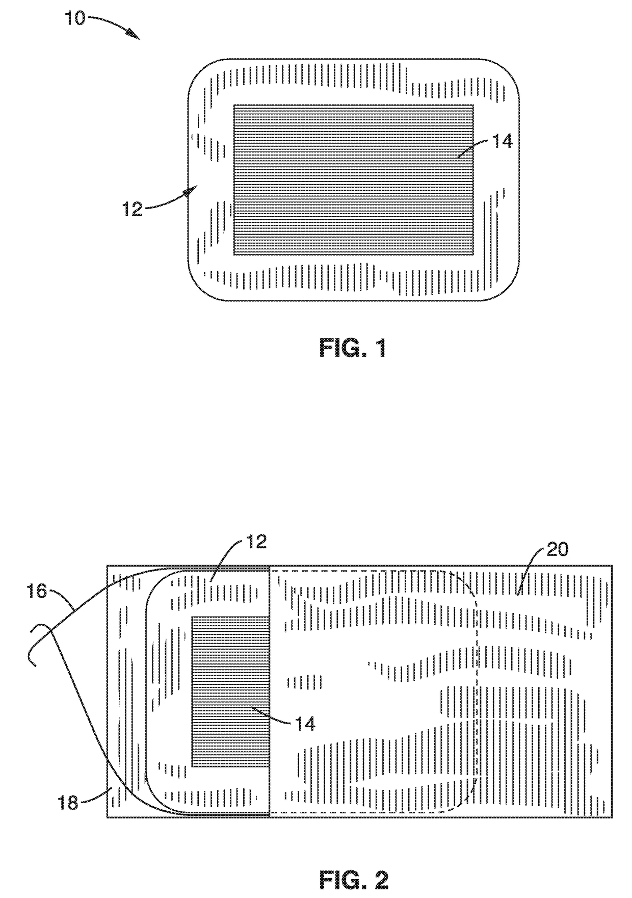
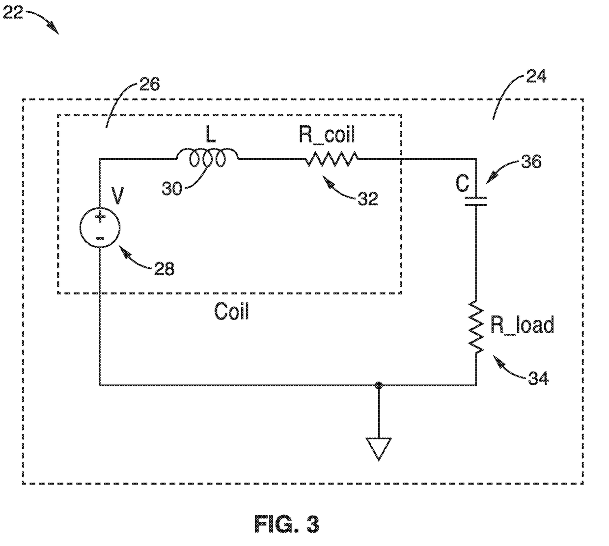
[0047]In order to demonstrate the operational principles of the apparatus and system, an energy harvester with a circuit shown generally in FIG. 4 with coils configured as shown generally in FIG. 2 was fabricated for testing.

[0048]One can model coils (e.g., with COMSOL) to find designs that maximize their open-circuit voltage, or that maximize their power output when the coil is loaded. Because flux condensers are coupled magnetically to the coil the coil's measured inductance will change, and therefore the optimum capacitance will change. The changing coil inductance that is observed upon testing can provide some indication of the effectiveness of a given flux condenser.

[0049]The coil that couples to the magnetic field produced by the powerline current (which, according to the Right-Hand Rule, encircles the current-carrying powerline conductor) can be made in three different ways. The first coil design was made by winding the wire of the coil on a non-magnetic form, producing an ai...

example 2

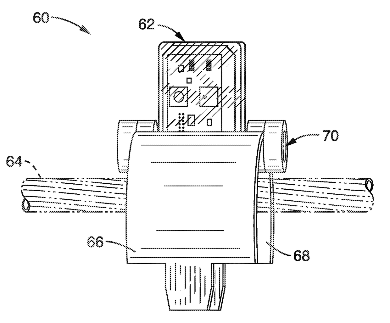
[0057]To further illustrate the apparatus and system, a printed circuit board with two commercial chemical vapor sensors along with a small radio chip to receive control signals and to transmit measured data. The harvester / sensor / radio embodiment is shown attached with conventional cable ties to a jacketed power distribution cable used for underground power distribution systems in FIG. 7 or to a typical bare aluminum overhead distribution power-line conductor in FIG. 8.

[0058]Since the harvester operates by coupling to the magnetic field near a current-carrying conductor, no ohmic contact need be made between the harvester and the conductor. Thus, the coil-based energy harvester, and sensors and communication devices associated with the harvester, could conveniently be contained in a weatherproof non-magnetic enclosure mounted near the conductor. As seen in the embodiment of FIG. 7 and FIG. 8, an inexpensive commercial plastic box was used to contain a harvester coil with a printed-c...


PUM


Abstract

An apparatus for harvesting power from a current carrying conductor without electrically contacting the conductor is provided. The apparatus employs a coil with core and flux concentrators of high magnetic permeability steel that redirect the time-varying magnetic flux of the conductor to interact more strongly with the coil, and increase the coil's output voltage and power. A voltage converter may be used with a DC voltage output that can continually charge batteries or supercapacitors as well as provide energy for sensors, accelerometers, long-range radios to transmit data on local powerline conditions, and LEDs and buzzers. The apparatus may also have powered environmental sensors for measuring the concentrations of airborne particulate matter such as diesel exhaust and smoke, as well as toxic gases, greenhouse gases, allergenic pollens etc. The apparatus has a housing that is oriented and coupled to the conductor with a coupling.

Description

CROSS-REFERENCE TO RELATED APPLICATIONS[0001]This application claims priority to, and the benefit of, U.S. provisional patent application Ser. No. 62 / 370,540 filed on Aug. 3, 2016, incorporated herein by reference in its entirety.STATEMENT REGARDING FEDERALLY SPONSORED RESEARCH OR DEVELOPMENT[0002]This invention was made with Government support under Contract Number D15PC00109 awarded by the Department of Homeland Security. The government has certain rights in the invention.INCORPORATION-BY-REFERENCE OF COMPUTER PROGRAM APPENDIX[0003]Not ApplicableBACKGROUND1. Technical Field[0004]The technology of this disclosure pertains generally to devices and methods for passive electricity generation and more particularly to an apparatus and methods for harvesting electrical energy from energized conductors carrying alternating currents, such as those on overhead and underground power lines and power-supplying conductors in offices and dwellings. A primary function of the harvester is to obtai...

Claims


Application Information

Patent Timeline
Patent Type & Authority Applications(United States)
IPC IPC(8): H02J50/12H02J7/04H02J7/02
CPCH02J50/12H02J7/025H02J7/04H04B1/02H04B3/54H01F38/14H01F38/28H02J50/001
Inventor WHITE, RICHARD M.WU, ZHIWEI
Owner RGT UNIV OF CALIFORNIA
Why Eureka
Try Eureka