Ophthalmic apparatus

a technology of ophthalmology and ophthalmology, which is applied in the field of ophthalmology equipment, can solve the problems of difficulty in checking or locating the opacity of the crystalline lens or other factors which causes the influence, eye refractive power, and inability to check, so as to facilitate the checking of the opacity of the crystalline lens and appropriately evalua

Active Publication Date: 2009-03-24
NIDEK CO LTD
View PDF8 Cites 4 Cited by
  • Summary
  • Abstract
  • Description
  • Claims
  • Application Information

AI Technical Summary

Benefits of technology

[0006]An object of the invention is to provide an ophthalmic apparatus capable of easily checking opacity of a crystalline lens or other factors, and more appropriately evaluating a measurement result on eye refractive power distribution or wavefront aberration.

Problems solved by technology

However, with such an apparatus, even when the mapping image shows an influence of opacity of a crystalline lens or other factors, it is difficult to check or locate the opacity of the crystalline lens or other factors which causes the influence.
However, the display of the diaphanoscopic image by such an apparatus is just used for checking in reliability of a measurement result on the eye refractive power, and does not enable checking variation of eye refractive power distribution and others of the examinee's eye caused by the an influence of the opacity of the a crystalline lens or other factors.

Method used


Image

  • Ophthalmic apparatus
  • Ophthalmic apparatus
  • Ophthalmic apparatus

Examples


Embodiment Construction

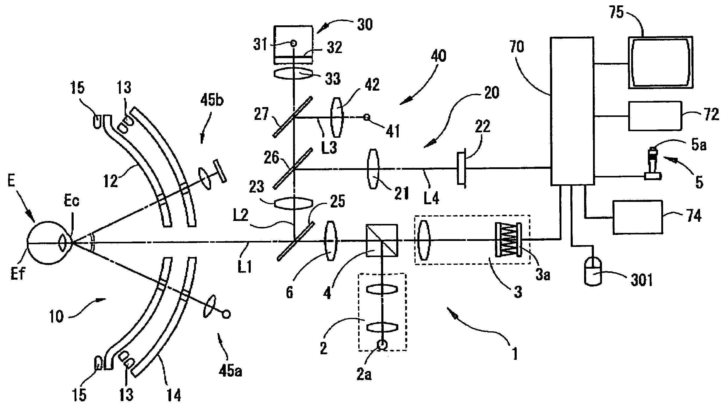
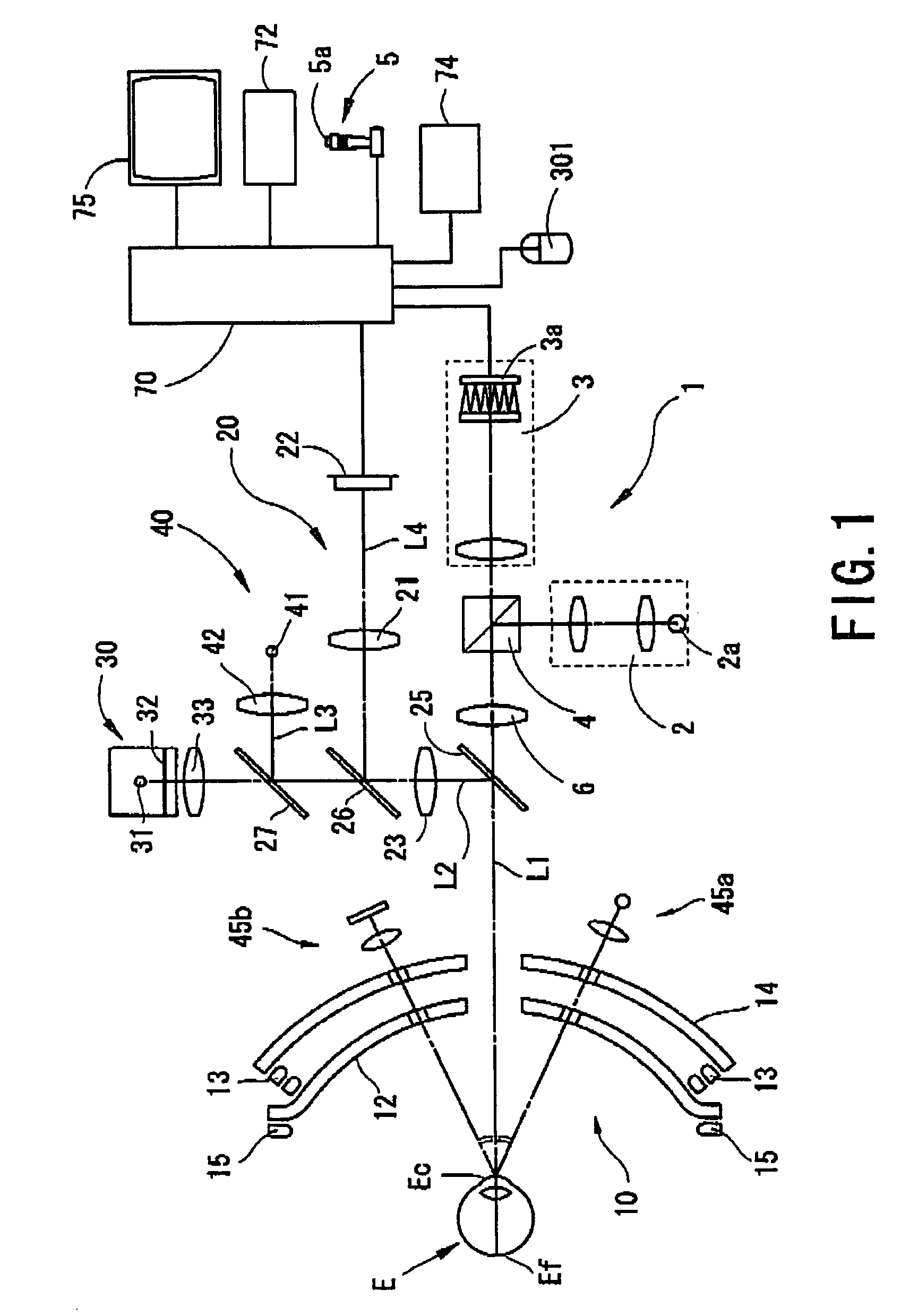
[0015]A detailed description of one preferred embodiment of an ophthalmic apparatus embodied by the present invention is provided below with reference to the accompanying drawings. FIG. 1 is a view showing a schematic configuration of an optical system and a control system of the ophthalmic apparatus according to the preferred embodiment of the present invention.

[0016]The optical system of the apparatus according to the present invention includes an optical system 10 which projects a ring-pattern target onto a cornea Ec of an examinee's eye E, an optical system 20 which picks up an image of an anterior segment of the eye E, an optical system 30 which presents a fixation target to the eye E, an optical system 40 which projects a target for alignment in right-and-left and up-and-down directions (hereinafter, X and Y directions) onto the cornea Ec, and an optical system 45a which projects a target for alignment in a back-and-forth direction (hereinafter, a Z direction), which is a work...


PUM


Abstract

An ophthalmic apparatus capable of easily checking opacity of a crystalline lens, and more appropriately evaluating a measurement result on eye refractive power distribution or wavefront aberration, which includes a measurement optical system for projecting measurement light onto a fundus of an examinee's eye and photo-receiving the measurement light reflected from the fundus so as to measure eye refractive power distribution or wavefront aberration, an illumination for an anterior segment, a first image-pickup optical system for picking up an image of the anterior segment, a projection optical system for projecting photographing light onto the fundus, a second image-pickup optical system for photo-receiving the photographing light so as to pick up a diaphanoscopic image, a monitor, a calculation part for obtaining a mapping image based on a result of the measurement, and a control part for displaying the mapping image and the diaphanoscopic image on one screen of the monitor.

Description

BACKGROUND OF THE INVENTION[0001]1. Field of the Invention[0002]The present invention relates to an ophthalmic apparatus which measures eye refractive power distribution or wavefront aberration of an examinee's eye.[0003]2. Description of Related Art[0004]Conventionally, there is known an ophthalmic apparatus which measures eye refractive power distribution or wavefront aberration of an examinee's eye by projecting measurement light onto a fundus of the eye and photo-receiving the measurement light reflected from the fundus. Such an apparatus displays a measurement result on the eye refractive power distribution or the wavefront aberration as a mapping image (see U.S. Pat. No. 5,907,388 corresponding to Japanese Patent Application Unexamined Publication No. Hei10-108837). However, with such an apparatus, even when the mapping image shows an influence of opacity of a crystalline lens or other factors, it is difficult to check or locate the opacity of the crystalline lens or other fac...

Claims


Application Information

Patent Timeline
Patent Type & Authority Patents(United States)
IPC IPC(8): A61B3/10
CPCA61B3/1173
Inventor FUJIEDA, MASANAO
Owner NIDEK CO LTD
Why Eureka
Try Eureka